
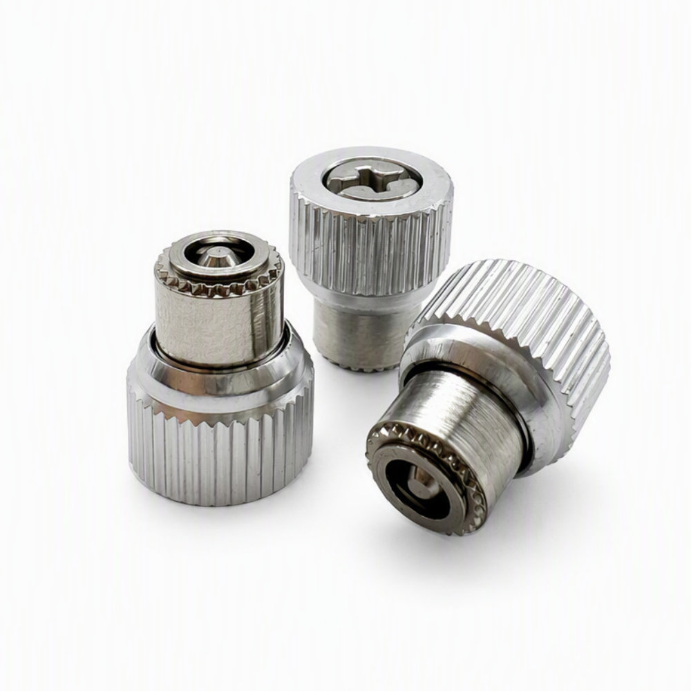
PF21-M3-0 Captive Panel Screw, Self-Clinching
- Part No : PF21-M3-0
-
- Product No.: PF21-M3-0
- Type: Self-clinching captive panel screw
- Thread: M3 x 0.5
- Catalog Code: 0
- Minimum Panel Thickness: 1.00 mm
- Mounting Hole: 5.56 mm, +0.08 mm tolerance
- A Max.: 0.97 mm
- T2 Nom.: 11.50 mm
- T1: 12.30 ±0.64 mm
- G: 4.00 ±0.64 mm
- C Max.: 5.54 mm
- E: 10.59 ±0.25 mm
- Recess Size: #1
- Minimum Edge Distance: 7.11 mm
Catalog reference dimensions; verify the approved drawing or sample before production.
- Inquiry now
Detailed description
Product Overview
The PF21-M3-0 captive panel screw is a self-clinching fastener for removable panel assemblies. The LAMBOOR catalog specifies an M3 x 0.5 thread, a 5.56 mm mounting hole and a minimum panel thickness of 1.00 mm. Its captive construction keeps the screw with the panel when it is released from the mating thread.
The pictured assembly has a silver knurled knob and cross recess for access by hand or screwdriver. The PF21 mounting arrangement is press-installed; it should not be selected using the flare-mount instructions of a different captive-screw family.
PF21-M3-0 Catalog Specifications
The following values are from the PF21/PF22 page of the LAMBOOR Standard Fastener Catalog V0.1, PF21 M3 code 0 entry. All dimensions are in millimeters. The catalog identifies these as manually measured reference data, with the actual product taking precedence. Use an approved drawing or sample for production acceptance.
| Specification | Value |
|---|---|
| Product number | PF21-M3-0 |
| Thread size and pitch | M3 x 0.5 |
| Installation | Self-clinching, press-installed |
| Catalog code | 0 |
| Minimum panel thickness | 1.00 mm |
| Mounting hole | 5.56 mm, +0.08 mm tolerance |
| A, maximum | 0.97 mm |
| T2, nominal | 11.50 mm |
| T1 | 12.30 ±0.64 mm |
| G | 4.00 ±0.64 mm |
| C, maximum | 5.54 mm |
| E | 10.59 ±0.25 mm |
| Recess size | #1 |
| Minimum edge distance | 7.11 mm |
Part Number and Component Materials
PF21 identifies the product series, M3 identifies the thread code, and 0 selects the catalog’s end/length code. Dimension letters refer to the PF21/PF22 drawing rather than to a universal captive-screw naming convention.
The catalog lists a steel retainer, aluminum knob and stainless steel screw for this family. Silver and black versions are shown, with other colors available by request. BL identifies the black option in the designation example. Combination slotted/cross-recess and cross-recess styles are listed; the M3 row gives recess size #1. Specify the required color and drive style when ordering. Color alone does not establish a plating type, coating thickness or corrosion rating.
Panel and Installation Review
Review the mounting-hole size, minimum panel thickness and minimum edge distance together. The catalog drawing shows a press acting on the knob with the sheet supported beneath the mounting position. Use tooling appropriate to the actual assembly, with clearance for the screw and support around the installation area.
Check panel material and hardness, installation force and tool geometry against the approved assembly requirements before production. The published catalog row does not provide numerical limits for these conditions. After installation, verify seating, screw travel, mating-thread engagement and access to the knob and recess. Do not treat the minimum panel thickness as a complete compatibility approval.
Frequently Asked Questions
Does code 0 mean the screw has no projection?
No. Code 0 selects a defined geometry, including G = 4.00 ±0.64 mm. In the M3 table, code 1 changes G to 5.70 ±0.64 mm and T1 to 14.00 ±0.64 mm. Choose the code from the required reach and assembly clearance, not by interpreting 0 as zero screw length.
Can PF22-M3-0 be used in the same panel?
Not without reviewing the sheet thickness. The PF22 M3 entry requires a minimum thickness of 1.50 mm and has A maximum 1.47 mm, compared with 1.00 mm and 0.97 mm for PF21. A panel suitable for PF21 is therefore not automatically suitable for PF22. Check the complete drawing and installation conditions before substitution.
Is the stainless steel screw evidence that the whole assembly is stainless steel?
No. The company catalog specifies three different component materials: a steel retainer, aluminum knob and stainless steel screw. If an assembly must meet a particular corrosion or material requirement, state it explicitly and review all components and their finishes. Do not approve an all-stainless requirement from the screw material or silver appearance alone.
Request a Quote
Provide PF21-M3-0, quantity, color and drive requirements, along with the panel material, thickness and mating-thread details. Include any required inspection or finish criteria. Ask for current price, availability, minimum order quantity and lead time in the quotation.



