
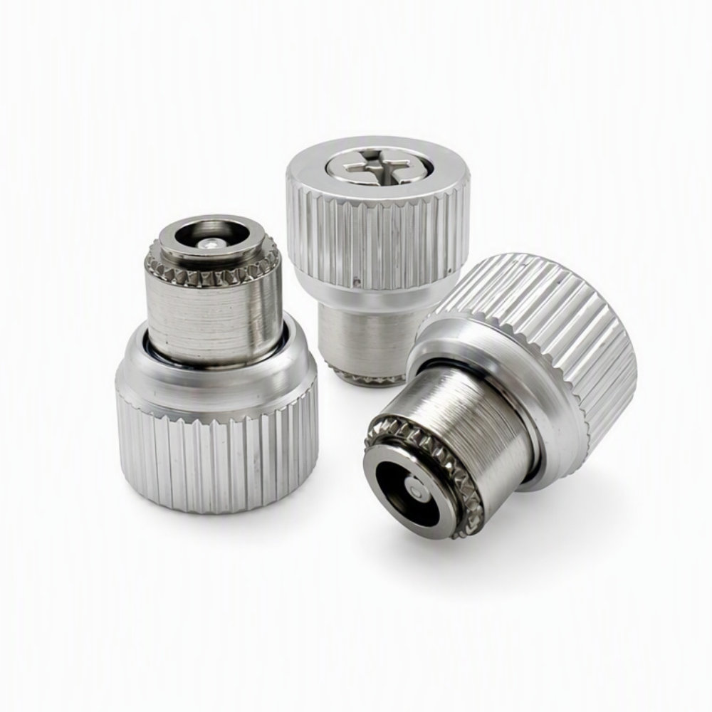
PF15-M3-0 Captive Panel Screw, Flare-Mounted
- Part No : PF15-M3-0
-
- Product No.: PF15-M3-0
- Type: Flare-mounted captive panel screw
- Thread: M3 x 0.5
- Catalog Code: 0
- Mounting Hole: 4.75 mm
- Panel Thickness: 0.8–1.5 mm
- A: 1.00 ±0.10 mm
- B: 0.40 ±0.01 mm
- C Max.: 4.73 mm
- G: 4.00 ±0.40 mm
- T1: 12.10 ±0.20 mm
- T2 Nom.: 11.30 mm
- E: 10.50 ±0.25 mm
Dimensions follow the LAMBOOR PF15 M3 code 0 catalog entry.
- Inquiry now
Detailed description
Product Overview
The PF15-M3-0 captive panel screw is a flare-mounted fastener for removable panels. The LAMBOOR configuration uses an M3 x 0.5 thread, a 4.75 mm mounting hole and a panel thickness range of 0.8–1.5 mm. Its captive construction keeps the screw with the panel during release from the mating thread.
The knurled knob provides a gripping surface, while the drive recess allows screwdriver access. This page specifies the LAMBOOR PF15 M3 code 0 configuration. Check its installation dimensions rather than relying on a matching part number alone when replacing an existing fastener.
Dimensions and Panel Requirements
Values below follow the PF15/PF25 page of the LAMBOOR Standard Fastener Catalog V0.1, PF15 M3 code 0 row. Dimension letters refer to that catalog drawing. All dimensions are in millimeters.
| Specification | Value |
|---|---|
| Product number | PF15-M3-0 |
| Thread size and pitch | M3 x 0.5 |
| Catalog code | 0 |
| Installation | Flare-mounted |
| Mounting hole diameter | 4.75 mm |
| Panel thickness | 0.8–1.5 mm |
| A | 1.00 ±0.10 mm |
| B | 0.40 ±0.01 mm |
| C, maximum | 4.73 mm |
| G | 4.00 ±0.40 mm |
| T1 | 12.10 ±0.20 mm |
| T2, nominal | 11.30 mm |
| E | 10.50 ±0.25 mm |
Material, Color and Drive Selection
The catalog lists two material configurations for this family: an aluminum retainer and aluminum knob with a stainless steel screw, or an all-stainless-steel construction. Specify the required configuration with the order; a silver appearance alone does not identify the material combination.
Silver and black versions are listed, with other colors available by request. BL is the black suffix in the catalog designation. Combination slotted/cross-recess and cross-recess drive styles are listed. State the required material, color and drive style when requesting a quotation. Color selection is not a coating-thickness or corrosion-performance specification.
Installation and Fit Review
Use the PF15 M3 mounting geometry and a flare-mount installation setup suited to the panel. Review the 4.75 mm hole together with the 0.8–1.5 mm panel range before making production panels. The catalog includes a 90° ±2° hole-preparation detail; use the complete drawing to establish its location and geometry rather than treating the angle alone as a machining instruction.
Provide access to the knob and drive recess. Check both the fastened and released positions against the mating component and available clearance. Screw engagement depends on the panel stack and mating thread, not just the G dimension. Use an approved drawing or sample to verify the final assembly before production.
Frequently Asked Questions
Does the final 0 mean that PF15-M3-0 has no screw projection?
No. It is a catalog selection code, not a zero-length dimension. For the PF15 M3 row, code 0 has G = 4.00 ±0.40 mm and T1 = 12.10 ±0.20 mm. Code 1 changes these values to 5.70 ±0.40 mm and 13.80 ±0.20 mm. Select the code by the required assembly reach and clearance.
Can PF25-M3-0 replace this part in the same panel?
Do not assume a direct substitution. The LAMBOOR catalog lists 0.8–1.5 mm panels for PF15 M3, but 1.5–2.5 mm panels for PF25 M3. PF25 code 0 also changes A to 1.80 ±0.10 mm, G to 4.70 ±0.40 mm and T1 to 12.80 ±0.20 mm. Review the complete mounting and clearance dimensions before changing series.
Is the same PF15-M3-0 designation enough to approve a replacement from another supplier?
No. A matching designation is a starting point, not proof of dimensional interchangeability. Compare the installation method, mounting hole, panel thickness, drawing dimensions, material configuration and drive style with this LAMBOOR specification. Include the existing fastener drawing or an approved sample in a replacement inquiry.
Request a Quote
Send PF15-M3-0, quantity, required material configuration, color and drive style, plus the panel thickness and mating-thread details. Include any mandatory finish, inspection or packaging requirements. Request current price, availability, minimum order quantity and lead time with the quotation.



