
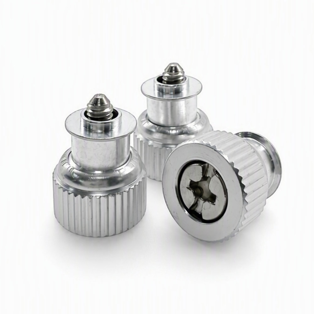
PF11MF-M3-1 Captive Panel Screw, Flare-Mounted
- Part No : PF11MF-M3-1
-
Product Number: PF11MF-M3-1
Product Type: Flare-Mounted Captive Panel Screw
Thread: M3 x 0.5
Screw Length Code: 1
Retainer / Knob: Aluminum / Aluminum
Screw Material: Stainless Steel
Knob Style: Knurled
Minimum Sheet Thickness: 0.97 mm
Mounting Hole: 4.75 mm
A: 1.05 mm
C: 4.73 mm maximum
E: 10.59 +/- 0.25 mm
G: 5.84 +/- 0.64 mm
P: 1.40 +/- 0.64 mm
T1 / T2: 7.87 / 11.94 mm nominal
Drive Size: #1Dimensions are catalog reference values. Confirm fit against the approved assembly drawing or sample.
- Inquiry now
Detailed description
Product Overview
The PF11MF-M3-1 captive panel screw combines an M3 x 0.5 screw with a knurled aluminum knob and an aluminum flare-mount retainer. The screw stays with the panel when released from the mating thread, helping keep the fastening hardware together during panel removal and refitting.
This model uses a stainless steel screw and the PF11MF flare-mounted construction. It is distinct from the self-clinching PF11 series: the mounting style and panel-hole requirements must match the selected fastener.
Key Features
- M3 x 0.5 external thread with the catalog’s self-guiding thread feature.
- Flare-mounted retainer for the corresponding panel preparation.
- Knurled knob for grip, with catalog-listed combination slotted/cross-recess and cross-recess drive options.
- Aluminum retainer and knob paired with a stainless steel screw.
- Length code 1 with defined lowered and raised screw projections.
Dimensions and Panel Requirements
The following values are from the PF11MF, M3, code 1 entry in the LAMBOOR Standard Fastener Catalog V0.1. All dimensions are in millimeters unless stated otherwise.
| Specification | Value |
|---|---|
| Product number | PF11MF-M3-1 |
| Thread size and pitch | M3 x 0.5 |
| Screw length code | 1 |
| Minimum sheet thickness | 0.97 mm |
| Mounting hole diameter | 4.75 mm |
| A | 1.05 mm |
| C, maximum | 4.73 mm |
| E, knob diameter | 10.59 +/- 0.25 mm |
| G, lowered-position projection | 5.84 +/- 0.64 mm |
| P, raised-position projection | 1.40 +/- 0.64 mm |
| T1, nominal lowered height | 7.87 mm |
| T2, nominal raised height | 11.94 mm |
| Catalog drive size | #1 |
The catalog identifies the dimensions as manually measured reference data. Confirm the mounting geometry and mating assembly against an approved drawing or sample before preparing production panels.
Understanding PF11MF-M3-1
In the catalog designation, PF11 identifies the product code, M denotes the self-guiding thread feature, and F denotes the flare-mount installation type. M3 specifies the M3 x 0.5 thread, while the final 1 selects the screw length code. It does not mean a 1 mm screw length.
The same M3 family also lists codes 0 and 2. Their G/P reference dimensions are 4.32/0 mm and 7.37/2.92 mm respectively, with a +/- 0.64 mm tolerance on each projection. Choose the code by the required screw reach and release clearance, not by the thread size alone.
Materials, Color and Drive
The PF11MF catalog page specifies an aluminum mounting retainer, an aluminum knob and a stainless steel screw. These are component-specific materials; the assembly is not described as an all-stainless-steel fastener.
Silver and black versions are listed, with other colors offered by request. The optional BL suffix identifies black. Specify the required color and either a combination slotted/cross-recess or cross-recess drive when requesting a quotation. Color alone does not define a coating specification.
Installation and Assembly Review
Use a panel preparation and flaring setup intended for this PF11MF configuration. Review the 4.75 mm mounting hole and 0.97 mm minimum sheet thickness together with the retainer geometry. Do not apply a self-clinching installation procedure simply because another panel screw has the same M3 thread.
Allow space around the knob for operation and access to the drive. Check the screw position both when fastened and when released, including clearance to the mating component. The mating thread depth and panel stack determine usable engagement; the projection dimensions alone do not establish the final engagement length.
Frequently Asked Questions
Can PF11MF-M3-1 use a panel already prepared for PF11-M3-1?
Do not treat it as a direct substitution. The LAMBOOR catalog lists a 4.75 mm mounting hole for PF11MF-M3-1, compared with 5.56 mm for the self-clinching PF11-M3-1. The retention methods also differ. Review the hole, panel thickness and installation tooling before changing between these two models.
Does the released screw withdraw completely behind the retainer face?
Do not assume full withdrawal from that face. The code 1 drawing gives a raised-position projection P of 1.40 +/- 0.64 mm. Check the drawing’s reference face against the panel stack and removal path so the remaining projection does not obstruct the mating component.
Can one installation force be used for every PF11MF assembly?
No universal force is specified on this catalog page. The setup must suit the panel and flaring tooling; a force taken from a different fastener is not an installation specification for this assembly. Provide the panel drawing and material when requesting installation guidance, and approve the setup with the selected parts before production.
Request a Quote
Send PF11MF-M3-1, quantity, required color and drive style, panel material and thickness, and any inspection or packaging requirements. Include the panel or assembly drawing for a fit review. Request current price, availability, minimum order quantity and lead time with the quotation.



