
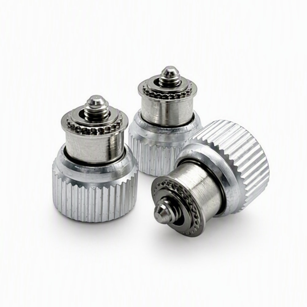
PF11-M3-1 Captive Panel Screw, Self-Clinching
- Part No : PF11-M3-1
-
Product Number: PF11-M3-1
Product Type: Self-Clinching Captive Panel Screw
Thread: M3 x 0.5
Bottom Code: 1
Knob: Knurled
Minimum Sheet Thickness: 0.92 mm (catalog table)
Mounting Hole: 5.56 mm
C: 5.54 mm maximum
E: 10.59 +/- 0.25 mm
G: 5.84 +/- 0.64 mm
P: 1.52 +/- 0.64 mm
T1 / T2: 7.87 / 11.43 mm nominal
Drive Size: #1
Minimum Edge Distance: 7.11 mmCatalog reference dimensions; verify the selected configuration against the approved drawing or sample.
- Inquiry now
Detailed description
Product Overview
The PF11-M3-1 captive panel screw is an M3 x 0.5 panel fastener with a knurled knob and a self-clinching mounting section. Its captive construction keeps the screw with the panel when the mating thread is released, supporting repeated panel access without a separate loose screw.
This model uses the PF11 series and bottom code 1. The complete part number identifies the configuration to request; the final code is not a screw length in millimeters.
Key Features
- M3 x 0.5 external thread for a matching metric female thread.
- Knurled knob for hand grip, with drive styles offered in the catalog.
- Self-clinching mounting for a prepared panel hole.
- Bottom code 1, with separate G and P projection dimensions.
Dimensions and Panel Requirements
The following reference values are from the PF11 metric M3, bottom-code-1 row in the LAMBOOR standard fastener catalog V0.1. Dimensions are in millimeters unless stated otherwise.
| Specification | Value |
|---|---|
| Product number | PF11-M3-1 |
| Thread size and pitch | M3 x 0.5 |
| Bottom code | 1 |
| Minimum sheet thickness, tabulated | 0.92 mm |
| Mounting hole diameter | 5.56 mm |
| C, maximum | 5.54 mm |
| E, knob diameter | 10.59 +/- 0.25 mm |
| G, projection in the lowered position | 5.84 +/- 0.64 mm |
| P, projection in the raised position | 1.52 +/- 0.64 mm |
| T1, nominal lowered height | 7.87 mm |
| T2, nominal raised height | 11.43 mm |
| Catalog drive size | #1 |
| Minimum edge distance | 7.11 mm |
The catalog identifies these measurements as reference data. Verify the selected mounting height, panel dimensions and mating assembly against the approved drawing or sample before releasing tooling or production.
Part Number and Configuration
PF11 identifies the product series, M3 identifies the M3 x 0.5 thread, and 1 identifies the bottom code. The catalog also lists codes 0 and 2 with different projection dimensions. Keep the complete PF11-M3-1 designation on inquiries and orders.
Material, Color and Drive Options
The catalog offers a steel mounting component with an aluminum knob and stainless steel screw, as well as all-stainless-steel and stainless-iron material configurations. Specify the required construction with the order. These family options do not identify a particular alloy grade or coating specification for every assembly.
Silver and black versions are listed, with other colors available by request. The suffix BL denotes black in the catalog designation. Combination slotted/cross-recess and cross-recess drive styles are also listed; specify the required drive configuration when ordering.
Installation and Use
Select this self-clinching version for a panel designed to retain the screw assembly while allowing the screw to engage a separate mating thread. Use the mounting-hole, panel-thickness and edge-distance values above when reviewing the panel layout, then verify the selected mounting configuration and tooling with the assembly drawing.
Check both raised and lowered positions. The knob needs operating clearance, and the screw must reach the mating thread without bottoming out. Material choice, panel geometry and required service conditions should be included in the assembly review.
Frequently Asked Questions
Can bottom code 0 or 2 replace code 1 in the same assembly?
Not without checking screw reach and clearance. For the M3 family, code 0 lists G = 4.32 mm and P = 0 mm; code 2 lists G = 7.37 mm and P = 3.05 mm. Both G and P carry a +/- 0.64 mm catalog tolerance. Compare these positions with the mating thread and available clearance before changing the code.
Does the G dimension equal the usable thread engagement?
No. G describes the screw projection shown in the catalog’s lowered-position drawing. Actual engagement also depends on the distance to the mating thread, its usable depth and the assembled panel stack. Review those dimensions together so the screw can fasten correctly without bottoming out.
Is a matching PF11-M3-1 number enough to approve a replacement?
The part number is the starting point, but replacement approval should also compare the mounting geometry, raised and lowered positions, material construction, drive and color. The LAMBOOR catalog offers several family configurations. Use the required drawing or a verified sample to check the complete assembly before substitution.
Request a Quote
Send PF11-M3-1, quantity, required material construction, color, drive style, panel material and thickness, and any inspection or packaging requirements. Include an assembly drawing when fit or replacement compatibility needs review. Ask for current price, availability, minimum order quantity and lead time with your quotation.



