
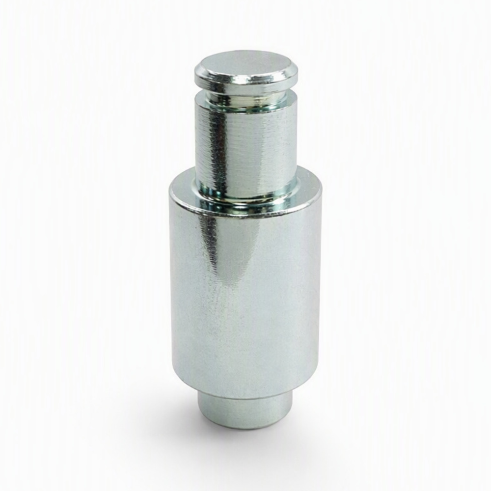
Custom CNC Turned Stepped Pins with Retaining Grooves
- Part No :
-
Product Type: Custom Stepped Pin
Manufacturing Process: CNC Turning
Material Options: Carbon Steel, Alloy Steel, Stainless Steel, Aluminum Alloy or Brass
Visible Features: Multi-Diameter Body, Round Head, Machined Shoulders and Circumferential Groove
Dimensions: Customized to Customer Drawing or Sample
Diameter and Length: According to Drawing Requirements
Retaining Groove: Width, Depth, Position, Radius and Retaining-Ring Fit According to Drawing
Tolerance and Fits: According to Drawing Requirements
Heat Treatment: Available for Steel Parts When Required by Drawing
Surface Finish Options: As Machined; Zinc or Electroless Nickel Plating for Steel; Passivation or Electropolishing for Stainless Steel; Anodizing for Aluminum; Polishing or Nickel Plating for Brass
Production Type: Made to Order
Quotation Basis: Drawing or Sample, Material, Finish, Quantity, Tolerances and Inspection Requirements - Inquiry now
Detailed description
Custom CNC Turned Stepped Pins with Retaining Grooves
These custom stepped pins are manufactured to customer drawings or samples. The turned geometry can combine a round head, multiple functional diameters, controlled shoulders, pilot sections, chamfers, radii and one or more circumferential grooves. Dimensions, fits, material, heat treatment and surface finish are selected for the assembly requirements rather than fixed to a standard size.
Typical Manufacturing Process
1. Drawing and Requirement Review
The datum system, functional diameters, shoulder lengths, groove geometry, edge condition, material, heat treatment, surface finish and inspection criteria are reviewed before machining.
2. Material and Blank Preparation
Bar stock is selected from carbon steel, alloy steel, stainless steel, aluminum alloy, brass or another machinable material specified for the order. The blank is cut with suitable allowance for turning, cutoff and any later finishing process.
3. Rough and Finish Turning
The main outside diameter, reduced sections, shoulders and end faces are turned in a controlled sequence. Machining allowances are planned around the final fit and any heat-treatment or coating requirement.
4. Head and Groove Machining
The round head, neck and circumferential retaining groove are formed to the drawing. Groove width, depth, root radius and axial position are controlled together because they determine compatibility with the specified retaining element and nearby shoulder.
5. Secondary Turning and Edge Finishing
The opposite end, pilot diameter, chamfers and radii are completed. Cutoff marks and burrs are removed without rounding functional shoulders or changing the groove profile.
6. Heat Treatment and Precision Finishing
Steel parts can receive drawing-specified hardening or other heat treatment. When the final diameter, runout, wear surface or surface condition requires it, grinding or another finishing operation can be planned after heat treatment.
7. Surface Treatment and Cleaning
The selected material-compatible finish is applied, precision fits and grooves are masked where required, and the parts are cleaned before final inspection.
8. Final Inspection
Inspection follows the approved drawing and can cover overall length, functional diameters, shoulder positions, groove dimensions, concentricity, runout, edge condition, surface condition and coating-sensitive fits.
Key Manufacturing Priorities
Coaxiality Between Stepped Diameters
Multiple diameters may serve different locating, guiding or rotating functions. A consistent datum and setup strategy helps control concentricity and runout between the large body, reduced stem and pilot section.
Shoulder Position and Squareness
Shoulders can control axial location. Tool deflection, nose radius and burr formation must be considered so shoulder length, face condition and transition radii remain consistent with the drawing.
Retaining-Groove Accuracy
The narrow groove is a critical local feature. Tool width, groove depth, root radius, axial position and burr control affect engagement with the retaining ring or mating component.
Rigidity and Surface Protection
Reduced diameters and finished surfaces can be marked or distorted by excessive clamping. Workholding, cutting sequence and part handling should protect functional surfaces throughout production.
Heat-Treatment and Coating Allowance
Heat treatment can change size or straightness, while plating and anodizing add material to exposed surfaces. The process plan should reserve the required dimensional allowance and define masking for precision fits and groove surfaces.
Material and Finish Selection
Carbon steel and alloy steel provide strength and wear resistance and can be heat treated when required. Zinc plating, electroless nickel plating, black oxide or phosphating can be selected according to corrosion, wear and appearance needs. High-strength steel plating should include appropriate hydrogen-embrittlement control.
Stainless steel is suitable where corrosion resistance is important. Passivation can improve the condition of the stainless surface, while electropolishing can support a smoother, cleaner finish.
Aluminum alloy reduces weight and can be supplied as machined, anodized, hard anodized or chemical-conversion coated. Anodizing changes surface dimensions and may show color variation, so fit allowance and appearance requirements should be defined in the drawing.
Brass offers good machinability and useful electrical or decorative properties. As-machined, polished, brushed or nickel-plated finishes can be selected to match the functional and appearance requirements.
For every material, coating buildup on precision diameters and groove surfaces should be considered. Powder coating is generally reserved for non-precision exposed surfaces and requires masking wherever parts must mate accurately.
Frequently Asked Questions
How should I identify the retaining ring for a custom stepped pin?
Provide the retaining-ring type and its manufacturer reference, standard or drawing together with the pin drawing. A similar shaft diameter or visible groove does not establish interchangeability. Mark the groove requirements that must match the selected retaining element and identify any assembly-access restrictions for review.
What information defines axial clearance after the ring is fitted?
Provide the mating-part stack and identify the shoulder or end face used as the axial reference. State the required assembled clearance and how it is to be checked, rather than treating a pin-only groove measurement as the complete assembly requirement. Include the mating drawing when the ring and shoulder locate another component.
Which requirements control when a sample and drawing differ?
Identify the controlling drawing revision and flag the differing groove, shoulder or diameter before quotation. If a sample shows wear or coating loss, state whether the replacement should reproduce the sample condition or follow a specified new-part geometry. Record the agreed dimensions and inspection basis before production.
Information Required for Quotation
Please provide a 2D or 3D drawing, or a physical sample, together with the material, dimensions, functional fits, groove details, tolerances, heat treatment, surface finish, order quantity and inspection requirements.
Review the quotation information checklist, then send your stepped-pin requirements.



