
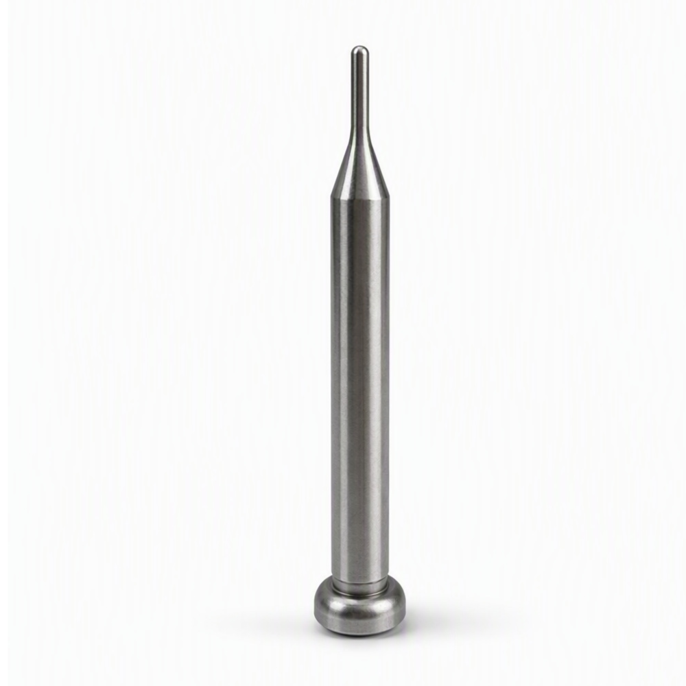
Custom CNC Turned Pin with Slender Tip and Flanged Head
- Part No :
-
Product Type Custom Turned Pin Manufacturing Process Turning Structure Long Cylindrical Body, Tapered Transition, Slender Tip and Flanged Head Material Options Stainless Steel, Carbon or Alloy Steel, Aluminum Alloys, Brass Dimensions Body and Tip Diameters, Lengths, Transition Profile and Head Geometry Customized to Drawing Tolerance Basis Approved Drawing, Functional Datums and Mating Requirements Surface Finish Options As Machined; Material-Compatible Finishes to Specification Production Type Made to Order Quotation Inputs Drawing or Sample, Material, Quantity and Inspection Requirements - Inquiry now
Detailed description
Custom Turned Pin with a Slender End Profile
This custom CNC turned pin has a long cylindrical body, a tapered transition to a slender rounded tip, and a flanged head at the opposite end. The part is manufactured to customer requirements rather than a fixed catalog specification. Body length, tip diameter, transition geometry and head dimensions are controlled by the approved drawing.
Typical Turning Process
A typical manufacturing route begins with selecting bar stock for the specified material and required machining allowance. Facing and rough turning establish the main reference surfaces. Controlled finish passes then produce the cylindrical body, transition and slender tip. The head and adjoining shoulder are completed using a workholding sequence appropriate to the drawing. The actual sequence depends on the dimensions, material and order requirements.
The small tip section needs attention to cutting forces and deflection. Suitable support, tool condition and finishing allowance are selected during process planning. Burr removal and cleaning should preserve the tip’s intended end form and transition rather than rounding away a controlled feature. Any specified heat treatment or surface finish is coordinated with final dimensional inspection.
Product-Specific Manufacturing Priorities
The relative positions of the body, tip and head matter more than a generic claim of precision. Identify the functional axis and datum face on the drawing, then specify straightness, runout or other geometric controls where the assembly needs them. The transition angle or radius and its axial position should be dimensioned separately from the slender tip’s usable length.
The head diameter, thickness, underside profile and shoulder location can affect clearance in the mating assembly. Workholding marks and handling damage on controlled surfaces should be addressed in the acceptance requirements. No load capacity, contact behavior or particular application is implied by this pin’s shape.
Material Options and Compatible Finishes
Stainless steel, carbon or alloy steel, aluminum alloys and brass are potential material families for drawing-based review. Select a grade according to strength, wear, corrosion resistance, weight and cost. A slender section may make stiffness and the specified heat-treatment condition especially relevant; those requirements must come from the design rather than the photograph.
As-machined surfaces may be specified. Compatible alternatives include passivation for stainless steel, zinc or electroless nickel plating for suitable steels, anodizing for aluminum, and polishing or nickel plating for brass. Finish selection should account for the working environment and surface requirements. Coating buildup must be considered on the tip and any fitted body section. Masking, final fit checks and, for plated high-strength steel, hydrogen-embrittlement controls should be agreed where applicable.
Inspection to the Approved Drawing
Inspection requirements may include overall length, body and tip diameters, slender-tip length, transition profile, head dimensions and shoulder location. Identify the surfaces requiring roughness control and the datum-based geometric tolerances. Check edge condition and handling marks against the specification, then assess final dimensions after any treatment that affects fit. Specify required first-article records or material documents during quotation review without assuming a fixed tolerance or test result.
FAQ
Should the rounded tip end be dimensioned separately?
Yes, when the end profile affects assembly or acceptance. Specify the end radius or other required form separately from the tip diameter and usable length. A rounded appearance does not establish the end’s exact geometry; add the profile requirement to the approved drawing before ordering.
Can the long body and slender tip use different acceptance criteria?
Yes, the drawing can assign separate requirements to the two sections. Identify each controlled length and diameter, then state any common datum relationship. This avoids imposing an unnecessary tolerance on the entire body when only the tip or a particular fitted section is functional.
How should the slender tip be protected during packing?
Request packing that prevents the tip from carrying stacking or handling loads. Individual separation or a suitable protective holder can be reviewed according to the geometry and material. Include any restrictions on tip contact, surface marks or corrosion-protection residues in the purchase requirements.
Quotation Information
Provide a 2D drawing and an optional 3D model or sample, plus the material grade, body and tip dimensions, transition details, head geometry, functional datums, tolerances, finish, order quantity and inspection requirements. Include operating conditions when they affect the design. LAMBOOR can review these inputs for a custom turning quotation.



