
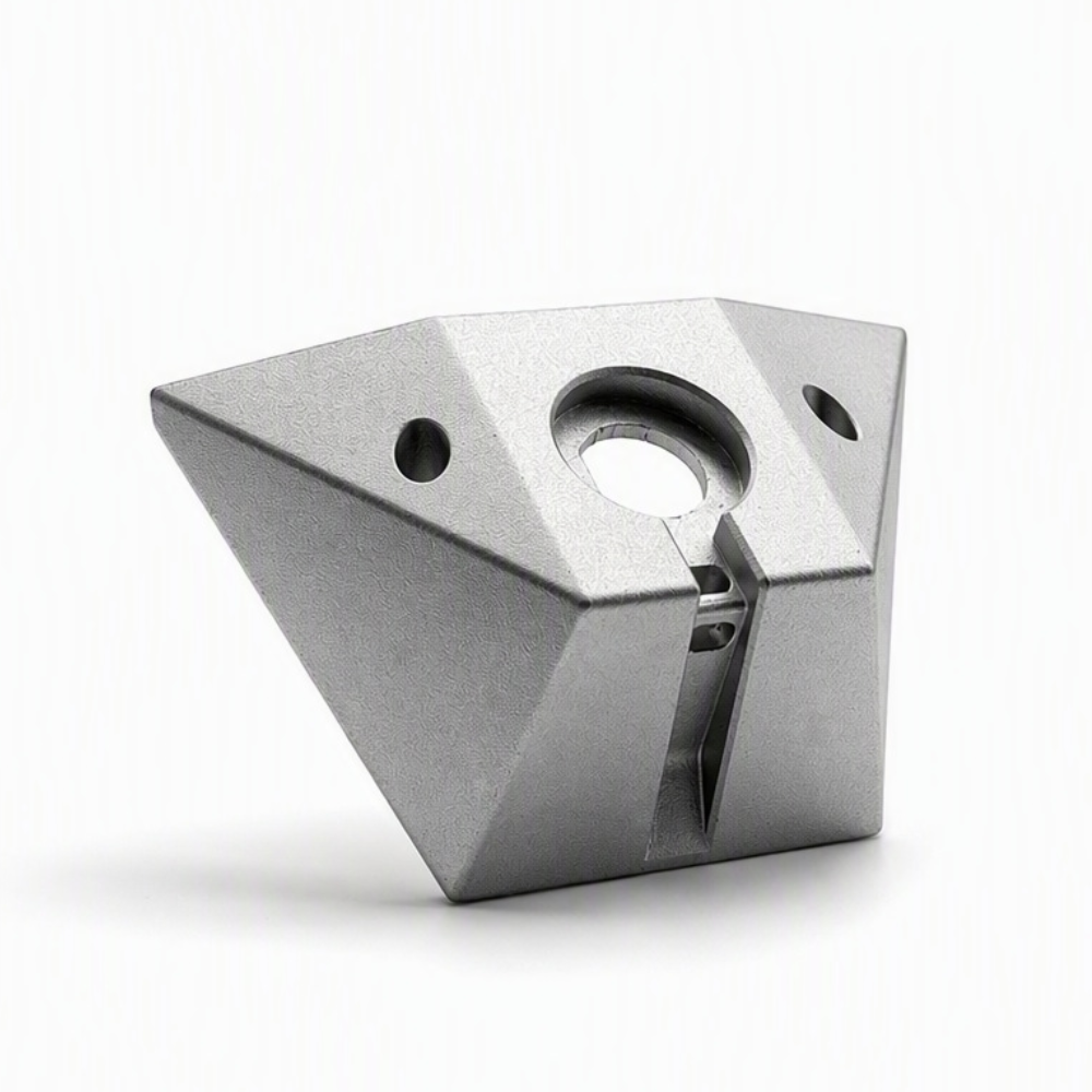
Custom CNC Machined Bracket with Split Bore and Mounting Holes
- Part No :
-
Product Type: Custom CNC Machined Bracket
Manufacturing Process: CNC Turning and Milling
Material: Specified in the approved drawing or material specification
Visible Features: Central Recessed Bore, Split Slot and Two Mounting Holes
Dimensions: Customized to Customer Drawing or Sample
Central Bore: Diameter, Recess, Fit and Datum Requirements as Specified
Split Slot: Width, Depth, Position and Edge Condition According to Drawing
Mounting Holes: Diameter, Position, Depth and Thread Requirements as Specified
Tolerance: According to Approved Drawing
Surface Finish: Specified in the approved drawing
Production Type: Made to Order
Quotation Basis: Drawing, Material, Quantity, Tolerances and Inspection Requirements - Inquiry now
Detailed description
Custom CNC Machined Bracket with Split Bore and Mounting Holes
This custom machined bracket has a block-shaped body with angled outer faces, a central recessed bore, a split slot and two visible mounting holes. The part is manufactured to customer documentation. Its final application, material grade, dimensions, hole details and fit requirements must be confirmed from the approved drawing or sample.
Because this is a made-to-order component, there are no fixed standard dimensions. The overall profile, central bore, recess, split-slot geometry, mounting-hole locations, tolerances, edge condition and surface finish are defined by the customer drawing.
Typical Manufacturing Process
1. Drawing and Material Review
The drawing, datum system, material grade, bore fit, recess, slot geometry, hole requirements, tolerances and inspection criteria are reviewed before production.
2. Blank Preparation
The specified stock or prepared blank is cut with suitable machining allowance. Material identity and blank condition are confirmed before machining.
3. Circular Feature Machining
According to the process plan and workholding method, turning or precision boring establishes the central bore and recessed circular feature. These surfaces may be used as important references for later milling operations.
4. External Profile Milling
The block profile, angled faces, steps and mounting surfaces are machined by CNC milling. A consistent datum strategy is required to control the relationship between the outer faces and the central bore.
5. Hole and Split-Slot Machining
The two visible holes, any specified cross-hole and the narrow split slot are machined to drawing. Hole diameter, depth, thread condition and functional relationship are not inferred from the photograph.
6. Deburring and Cleaning
Burrs at the bore, recess, split slot and intersecting holes are removed while protecting functional edges and mating surfaces. The part is cleaned before any specified surface treatment.
7. Final Inspection
Inspection is based on the approved drawing and may include the external profile, central-bore diameter and fit, recess depth and concentricity, slot width and position, hole spacing, datum relationships and surface condition.
Key Manufacturing Considerations
Datum Transfer Between Turning and Milling
The circular bore and non-rotational bracket faces must share a controlled datum strategy. Repositioning error can affect bore-to-hole location, symmetry and mounting alignment.
Split-Bore Distortion
Machining the slot reduces local rigidity and may allow the bore to move after clamping pressure is released. The operation sequence, stock allowance and workholding pressure should be planned around the specified final bore size and fit.
Recess Concentricity and Depth
The circular recess must remain concentric with the bore and at the required depth. Tool runout, datum setup and chip evacuation can influence this relationship.
Narrow Slot and Intersecting Features
The split slot and any intersecting hole provide limited tool access and can create burrs at internal edges. Slot width, corner condition and permitted edge break should be stated on the drawing.
Information Required for Quotation
Please provide a 2D or 3D drawing, or a physical sample, together with the material grade, dimensions, bore and recess details, slot requirements, mounting-hole specifications, tolerances, surface finish, order quantity and inspection requirements.



