
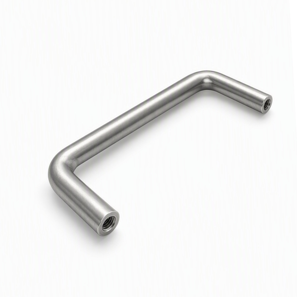
Custom CNC Machined U-Shaped Bar with Internal Threads
- Part No :
-
Item Specification Product Type Custom U-shaped round-profile bar with internally threaded ends Manufacturing Process Turning and milling; complete profile route according to the approved drawing Structure Long connecting section, two curved corners and two short end sections Thread Requirements Internal threads at both free ends; thread designation, class and usable depth customized to drawing Material Options Stainless steel, carbon or alloy steel, aluminum alloys and brass, subject to design review Surface Finish Options Brushing or polishing; stainless steel passivation; compatible steel plating or aluminum anodizing Profile Dimensions Section size, end-center spacing, leg lengths and corner geometry according to drawing Tolerance and Inspection Drawing-defined thread, end-position, profile and surface acceptance requirements Supply and Quotation Made to order; provide drawing or sample, mating-thread details, material, finish and quantity - Inquiry now
Detailed description
Internally Threaded U-Shaped Bar Overview
This custom CNC machined U-shaped bar combines a long round-profile connecting section with two curved corners and short end sections. Internal threads are visible at both free ends. The threaded end interfaces distinguish this component from a plain-ended U-shaped bar or a conventional externally threaded U-bolt.
LAMBOOR supplies the part as a non-standard, drawing-controlled turning and milling component. Section size, leg geometry and thread details are specified for each design. The U-shaped outline is a structural description, not a claim that the component is a lifting handle, a certified attachment or a load-rated fastener.
Typical Machining and Threading Sequence
A typical workflow starts with the approved profile and thread drawings. Material and blank preparation, together with the route used to produce the overall shape, are reviewed before local turning and milling operations. The end faces and internal thread features are then machined as required by the drawing. Edge finishing, compatible surface treatment and final inspection complete the planned sequence. The exact production route depends on the geometry and order specification.
Access to each short end is an important setup consideration. The workholding arrangement should locate the thread axis while supporting the round-profile body without distorting the end positions. Machining the threads does not by itself establish that the two interfaces will align with an assembly; their position and orientation also require drawing control.
Thread Interfaces and Profile Priorities
For each internal thread, specify the designation, pitch, class, usable thread depth and entry treatment. Distinguish the usable engagement length from the drilled-hole depth and any thread runout. The end faces and thread axes should be related to the chosen datums so the mating threaded parts can be assessed against the complete U-shaped geometry.
Other priorities include end-center spacing, leg length, local section size, corner transitions and any required planar relationship between the ends. Burr removal at the thread entries must preserve the thread form. When both ends engage another assembly, the drawing should address access for the mating fasteners and their available engagement, rather than assuming compatibility from a similar overall shape.
Material and Compatible Finish Options
Stainless steel, carbon or alloy steel, aluminum alloys and brass are possible material families, subject to the approved design and process review. Strength, corrosion exposure, weight, thread durability, appearance and cost influence selection. The specified alloy and condition should be stated on the drawing or purchase specification.
Finish options depend on the material. Brushing or polishing may be considered for appearance, passivation for stainless steel, compatible plating for steels, and anodizing for aluminum. Internal threads may require masking or a controlled finishing allowance; the inspection stage and gauge requirements should therefore be agreed in relation to the final coating. If high-strength steel is plated, hydrogen-embrittlement controls must be addressed. A surface finish is not a substitute for a defined material or mechanical requirement.
Inspection and Information for Quotation
A drawing-based inspection plan should cover the complete profile, end-center spacing, end-face condition and specified thread acceptance. Thread checks must use the designated thread specification rather than a visually similar screw. Dimensional and appearance records can be defined for the order without assigning an unsupported universal tolerance to this custom component.
Send the profile drawing, both thread callouts, mating-part details, material, finish and required quantity for quotation. Identify the critical interfaces and revision level. Where the two ends have different requirements, mark them individually so the machining and inspection plan can distinguish them.
Frequently Asked Questions
Can a U-bolt be used as a direct replacement?
Not solely on the basis of the U shape. A conventional U-bolt has external threaded legs, whereas this component has internal end threads. Any replacement requires review of the mating interface, dimensions and design requirements, not just the outline.
Can the two ends have different thread sizes or depths?
Yes, differing end specifications can be reviewed for a custom version. Label the ends separately and specify each thread designation and usable depth. The available section and local geometry must support the proposed change.
Does the threaded-bar design define a tightening torque?
No. A torque value depends on the selected materials, mating fasteners, engagement, lubrication and joint design. Provide those conditions for an engineering review; the product image and thread appearance do not establish an assembly torque.



