
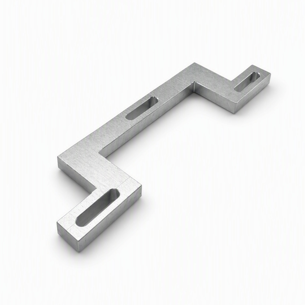
Custom Machined Bracket with Offset Profile and Three Slots
- Part No :
-
- Product Type: Custom Machined Bracket
- Manufacturing Process: CNC Turning and Milling
- Structure: Flat Offset Profile with Three Elongated Slots
- Material Options: Aluminum Alloy, Stainless Steel, Carbon or Alloy Steel, or Brass
- Profile, Thickness and Slots: Customized to Drawing
- Datums and Tolerances: According to Drawing Requirements
- Surface Finish Options: Material-Compatible Machined, Anodized, Passivated or Plated Finishes
- Production Type: Made to Order
- Quotation Inputs: Drawing, Material Grade, Mating Fasteners, Finish, Quantity and Inspection Requirements
- Inquiry now
Detailed description
This custom machined bracket has a flat offset outline and three elongated, rounded-end slots distributed along the body and end sections. LAMBOOR supplies the non-standard part through CNC turning and milling to customer drawings. The profile, thickness and slot arrangement can be specified for the mating assembly rather than selected from a fixed catalog size.
Typical Manufacturing Route
A typical route begins with drawing review, stock selection and preparation of reference surfaces. The machining plan assigns turning and milling operations according to the approved blank and drawing. Profile milling and slot machining establish the stepped outline, straight sections and rounded slot ends. The visible flat shape does not require every surface to be produced by turning. Deburring, cleaning, compatible surface treatment and final dimensional inspection complete the route.
Profile and Slot Control
The long connecting section and offset end portions require clear datum references. Slot locations should be dimensioned from functional references, not accumulated from successive edges. Specify slot width, length, end radius, spacing and orientation together with the minimum material remaining around each slot. The mounting faces and overall flatness matter where the bracket is clamped against another component.
Workholding should support the long section without bending it or marking the contact surfaces. Machining and deburring must preserve the slot boundaries and inside profile corners. A large edge break can change usable slot travel or reduce fastener contact area, so functional edge requirements should be stated separately from cosmetic rounding.
Material and Surface Finish Options
Aluminum alloys can be considered where low weight is important; stainless steel where corrosion resistance is a priority; carbon or alloy steel where strength, wear or cost favors it; and brass where machinability or specific electrical requirements justify the choice. The actual grade and condition depend on the load path, remaining section around the slots, mating materials and operating environment.
As-machined surfaces are an option. Aluminum can use anodizing, hard anodizing or bead blasting; stainless steel can use passivation, brushing or electropolishing; suitable steels can use zinc or nickel plating, phosphating or black oxide; and brass can use polishing or nickel plating. Specify compatible treatment and masking on contact faces and slots. Coating buildup reduces slot clearance, anodized color can vary, and black oxide needs suitable supplementary corrosion protection. High-strength steel plating may require hydrogen-embrittlement controls. Powder coating should not cover an unmasked precision interface.
Customization and Inspection
Define the complete outline, thickness, slot geometry, flatness, functional datums and any critical surface roughness on the drawing. Inspection requirements should address slot position and width, contact-face condition and burr-free edges. Specify whether acceptance dimensions apply before or after treatment, together with any first-article or dimensional-report requirements.
FAQ
Do the three slots provide a defined adjustment range?
Only when the mating fasteners and assembly are defined. Usable travel depends on slot length, fastener diameter, end clearance and surrounding interference. Show the intended range and both end positions on the drawing or assembly model. The slot length alone is not an adjustment-performance specification.
Can the bracket be clamped at any point along a slot?
The design must establish the permitted clamping positions. Fastener head or washer coverage, edge distance, contact-face area and the remaining section affect suitability. Provide the mating hardware and load direction for review; do not assume that a geometrically possible position has the same strength as another position.
What should be specified if several brackets must align as a set?
Define common functional datums and the permitted relationship between the slots and mounting faces. Identify whether parts are interchangeable or supplied as matched sets, and state any assembly inspection requirement. This prevents separate slot-length checks from being mistaken for verification of the complete multi-part alignment.
Request a Quotation
Send a dimensioned drawing and available 3D model, material grade, quantity, finish and inspection requirements. Include the mating hardware, critical slot positions and usable movement envelope. State any sample approval, marking or surface-protection packaging requirements.



