
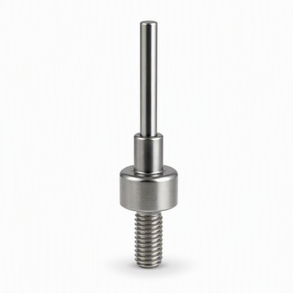
Custom Stepped Shaft with Threaded End and Long Pin
- Part No :
-
- Product Type: Custom Stepped Shaft
- Manufacturing Process: CNC Turning
- Structure: Long Smooth Pin, Stepped Shoulders and External Threaded End
- Material Options: Stainless Steel, Carbon or Alloy Steel, Aluminum Alloy or Brass
- Surface Finish Options: Material-Compatible Machined, Passivated, Plated or Anodized Finishes
- Diameters, Lengths and Thread: Customized to Drawing
- Fits and Tolerances: According to Drawing Requirements
- Production Type: Made to Order
- Quotation Inputs: Drawing, Material Grade, Thread Specification, Finish, Critical Fits and Quantity
- Inquiry now
Detailed description
This custom stepped shaft combines a long smooth pin, two larger shoulder sections and an external threaded end. LAMBOOR supplies the component to customer drawings rather than a fixed catalog size. The cylindrical steps, pin length, thread and locating faces can be specified together to match the mating assembly.
Typical Turning Process
A typical route starts with drawing review and preparation of a suitable blank. Facing and turning establish the reference axis, shoulder diameters and axial positions. The slender pin requires suitable support and a cutting sequence that limits deflection. The threaded end is produced to the specified thread form, followed by edge finishing, cleaning, any selected treatment and final inspection. Workholding and the need for further finishing depend on material, dimensions and drawing requirements.
Critical Features to Define
- Long pin: Specify diameter, straightness, usable length and surface condition where it engages a mating hole.
- Shoulders: Identify the locating face and the axial relationship between steps. Define corner radii or reliefs where a mating component must seat fully.
- Thread: State the designation, pitch, tolerance class, usable engagement length and permissible runout.
- Axis relationship: Define relevant geometric controls between the pin, shoulders and thread instead of applying an unspecified overall precision claim.
Materials and Compatible Finishes
Stainless steel may suit corrosion-focused designs; carbon or alloy steel can be considered for strength and wear requirements. Aluminum alloys offer lower weight, while brass may suit machinability or specific electrical requirements. The selected grade, condition and any heat treatment should be stated on the drawing.
Finish choices include an as-machined surface, stainless-steel passivation, suitable steel plating, or aluminum anodizing. Plating and anodizing require dimensional allowance on the pin and thread. Black oxide on a compatible steel is an option where its limited corrosion protection is acceptable with appropriate supplementary protection. High-strength steel plating can require hydrogen-embrittlement controls. Do not specify thick powder coating on an unmasked precision pin or thread.
Drawing-Based Inspection
Inspection requirements should distinguish the locating diameters, shoulder lengths and thread from noncritical surfaces. Specify the inspection condition before or after treatment, thread acceptance method, relevant geometric tolerances and report needs. The drawing, not the photograph, establishes the required fit and acceptance criteria.
FAQ
Does the long pin make this a locating or load-bearing shaft?
Its role is determined by the assembly design, not by the stepped shape alone. A locating use, sliding fit or loaded connection requires different fit, material and verification conditions. Provide the mating arrangement, loads and movement requirements so the design can be assessed against the intended function.
How can a mating part seat against the shoulder without fouling the corner?
Specify a compatible corner radius, relief or mating chamfer at the shoulder transition. A sharp corner shown in a simplified drawing is not enough to define contact. Include the intended seating face and available clearance so the shoulder can be manufactured and inspected without interference at its root.
Should a replacement be ordered by thread size alone?
No. Matching the thread does not establish compatibility of the long pin or the shoulder stack. Supply the pin fit, locating-face distances, thread engagement and mating clearances together. Where an existing part is the reference, identify the functional dimensions and required inspection rather than relying only on the threaded end.
Request a Quotation
Provide a dimensioned 2D drawing and, where available, a 3D model, material grade, thread specification, surface treatment and quantity. Mark critical locating features, report requirements and any sample-approval or protective-packaging needs.



