
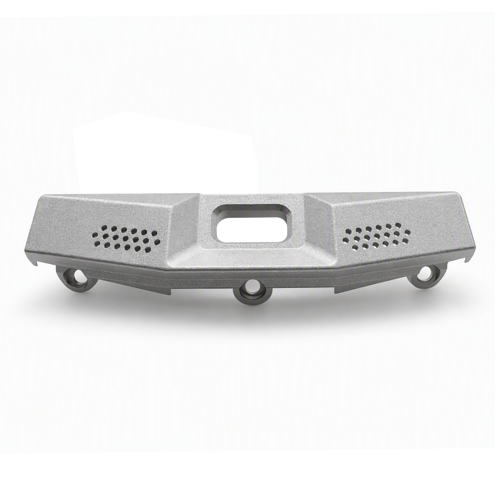
Custom CNC Machined Bracket with Hole Arrays and Mounting Lugs
- Part No :
-
- Product Type: Custom CNC Machined Bracket
- Manufacturing Process: CNC Turning, Milling and Drilling
- Structure: Contoured Body, Central Rounded-Rectangular Cutout, Two Small-Hole Arrays, Three Mounting Lugs
- Material Options: Aluminum Alloy, Stainless Steel, Carbon Steel or Alloy Steel
- Surface Finish Options: Material-Compatible Machined, Blasted, Anodized, Passivated or Plated Finishes
- Dimensions and Hole Pattern: Customized to Drawing
- Tolerances and Inspection: According to Drawing Requirements
- Production Type: Made to Order
- Quotation Inputs: 2D/3D Drawing, Material, Finish, Critical Tolerances, Inspection Requirements and Quantity
- Inquiry now
Detailed description
This custom CNC machined bracket features a long contoured body, a central rounded-rectangular cutout, two small-hole arrays and three lower mounting lugs. LAMBOOR supplies drawing-based custom metal parts, with the bracket geometry, material and finish selected for the mating assembly. This is a made-to-order component rather than a standard fastener with fixed catalog dimensions.
Typical Manufacturing Process
A typical route begins with drawing review and selection of a suitable blank. Reference surfaces are established before machining the external contour, recessed areas and mounting interfaces. CNC milling and drilling form the central cutout, hole arrays and lug holes; turning is used where the approved design calls for rotational features. The sequence and workholding depend on the blank, material and drawing. Deburring, cleaning, specified surface treatment and final inspection complete the route.
Machining Priorities for This Bracket
- Datum consistency: Define the relationship between the three mounting holes, central opening and repeated hole groups so that separate setups preserve the required alignment.
- Workholding and distortion: Support the elongated body and thinner sections without marking finished faces or distorting the mounting interfaces.
- Hole-array quality: Control the specified diameter, spacing and edge condition. Remove burrs from both sides without unnecessarily enlarging the holes.
- Cutout and contour: Specify corner radii, surrounding wall sections and any profile requirements that affect the mating assembly or tool access.
Material Selection
Options include aluminum alloys, stainless steels, carbon steels and alloy steels. Aluminum can be considered when weight and an anodized finish matter; stainless steel when corrosion resistance is a priority; carbon or alloy steel when strength, wear or cost requirements favor it. Select the grade and condition against the actual loads, environment and mating materials, and specify them in the production drawing.
Compatible Surface Finishes
For aluminum, options include an as-machined finish, bead blasting, anodizing, hard anodizing or chemical conversion coating. Anodizing allowance and cosmetic color expectations should be defined. Stainless steel options include passivation, brushing or electropolishing. Carbon and alloy steels can use zinc plating, electroless nickel plating, black oxide or phosphating where suitable. Black oxide requires appropriate supplementary corrosion protection, and plating high-strength steel may require hydrogen-embrittlement controls.
Specify coating thickness, masking and acceptance criteria for the mounting holes, mating faces and small-hole arrays. Powder coating may be considered where compatible with the chosen metal and service requirements, but precision interfaces require suitable masking and dimensional allowance.
Drawing-Controlled Customization and Inspection
The drawing controls the overall contour, cutout, hole diameters and pattern, mounting-lug geometry, edge treatment and finish. Identify critical datums, positional or profile tolerances, fit requirements and inspection documentation instead of applying an unsupported blanket tolerance. Inspection planning should address the mounting-hole relationship, hole arrays, cutout profile, burr condition and finish-protected interfaces. Include sample approval or first-article requirements in the RFQ when applicable.
FAQ
Are the two hole arrays intended for ventilation?
The hole arrays are configurable drawing features, not a specified ventilation rating. Their intended function depends on the assembly design. If airflow, drainage, screening or fastening is required, include the relevant function and acceptance criteria with the drawing; hole appearance alone does not establish airflow capacity or performance.
Can this bracket replace an existing part using only a photograph?
A photograph is useful as a reference but does not define an interchangeable replacement. Provide the mating-interface dimensions, mounting-hole pattern and datums, or a dimensioned drawing and sample. Identify which faces and holes must fit the existing assembly. Replacement suitability needs those requirements and dimensional verification, not visual similarity alone.
How should the small holes be specified if the bracket will be coated?
State whether the required hole size applies before or after finishing. Include coating thickness and masking requirements where they affect the finished opening. For these repeated small holes, also define allowable burrs and coating obstruction. This lets the machining and finishing plan address the usable opening rather than only the drilled diameter.
Request a Drawing-Based Quotation
Send a 2D drawing and, where available, a 3D model, together with the material grade, surface finish, critical dimensions and tolerances, inspection requirements and quantity. Highlight the interfaces that locate the bracket in the assembly and any first-article or packaging requirements. These details allow the manufacturing route and quotation to be assessed against the actual design.



