
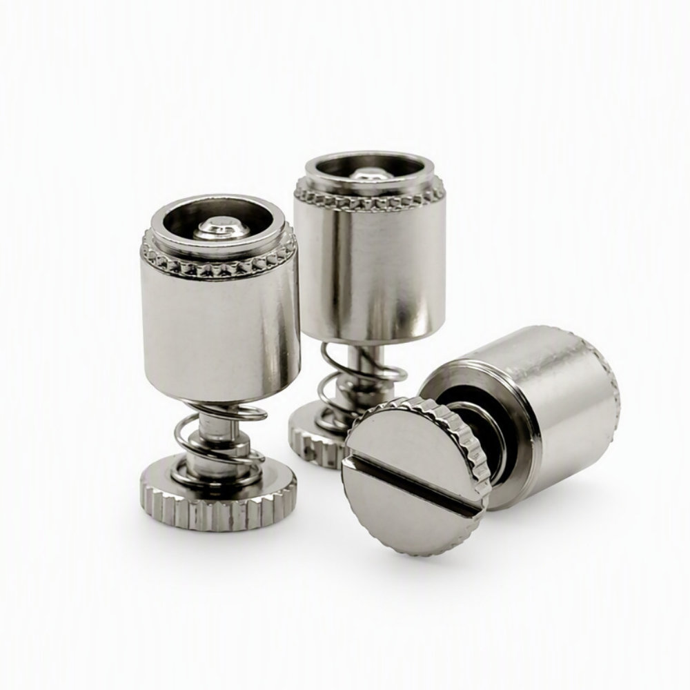
PFS2-M3-40 Captive Panel Screw, Spring-Loaded Steel
- Part No : PFS2-M3-40
-
- Part Number: PFS2-M3-40
- Product Type: Spring-loaded self-clinching captive panel screw
- Catalog Material Family: Steel
- Thread: M3 × 0.5
- Screw Length Code: 40
- Minimum Sheet Thickness: 1.53 mm
- Mounting Hole: 6.73 mm
- Minimum Edge Distance: 6.35 mm
- Inquiry now
Detailed description
Steel spring-loaded captive fastening
The PFS2-M3-40 captive panel screw is a steel-family standard fastener with an M3 × 0.5 thread, a slotted screw head and a spring-loaded assembly. Its self-clinching retainer provides the panel mounting interface, while the captive screw supports repeated opening without treating the screw as separate loose hardware.
The exposed spring and accessible screw head are visible in the product image. This construction should be evaluated together with the panel layout: allow clearance for the released screw, driver access and the mating threaded component, rather than selecting from thread size alone.
PFS2-M3-40 catalog specifications
| Parameter | Catalog value |
|---|---|
| Material family | Steel |
| Thread | M3 × 0.5 |
| Screw length code | 40 |
| A | 1.53 mm |
| Minimum sheet thickness | 1.53 mm |
| Mounting hole diameter | 6.73 mm |
| C, maximum | 6.71 mm |
| E | 7.92 ±0.25 mm |
| G | 6.4 ±0.4 mm |
| H | 1.83 ±0.13 mm |
| P | 0 ±0.64 mm |
| T1, nominal | 9.14 mm |
| T2, nominal | 13.72 mm |
| Minimum hole-center-to-edge distance | 6.35 mm |
Source: LAMBOOR Standard Fasteners Catalog V0.1, printed page 11 (PDF page 16). Dimension letters refer to the catalog drawing. The catalog’s measured values are for reference; the actual product governs.
Selection and installation review
Check the sheet thickness, mounting hole and edge distance against the panel drawing. Review the screw’s operating clearance and mating-thread position before choosing this length code. Define sheet material and the intended installation process with the assembly requirements; this dimensional table is not an installation-force or tightening-torque specification.
Frequently asked questions
Does the 40 suffix mean a 40 mm screw?
No. It is the catalog’s screw length code. Use the lettered dimensions and drawing to assess the actual assembly; do not enter 40 mm as the screw length on a purchase order.
Is PFS2 the stainless-steel version of PFC2?
No. The LAMBOOR catalog identifies PFS2 in the steel column and PFC2 in the stainless-steel column. If stainless material is required, review the appropriate catalog model instead of changing the material description for PFS2.
Can the released-height dimension be used as thread engagement?
No. T2 describes a catalog assembly dimension, not engagement with the mating thread. Engagement depends on the panel stack and mating-part position and should be checked on the assembly drawing.
Quotation information
Specify PFS2-M3-40, quantity and the panel material and thickness. Provide the panel and mating-part drawings plus any finish or inspection requirements so the requested configuration can be reviewed.



