APPLICATION GUIDE
Spring Clips and Wire Forms for Component Retention
Spring clips and wire forms can be considered for retaining and positioning components within a mechanical assembly. Choosing a useful geometry starts with the mating part, the required movement and the way the clip is installed or removed, rather than the outline of an isolated product photograph.
LAMBOOR offers drawing-based spring and wire-forming components. This application guide explains the information needed to review a retention or positioning project, using our special-shaped bent wire clips as a product example. The illustrated parts do not establish a load rating or document a specific customer installation.
Define what the component must do
Separate the functions of locating, retaining and allowing movement. A locating feature establishes a position; a retaining feature resists separation in a specified direction. A spring element may also need to move during assembly or operation. State which of these functions is required and identify the mating surfaces involved.
For example, a removable subassembly may need a defined insertion path and a retained final position. A locating arrangement may instead need clearance for assembly without continuous clamping. These are design scenarios for evaluation, not claims that one illustrated clip is suitable for both.
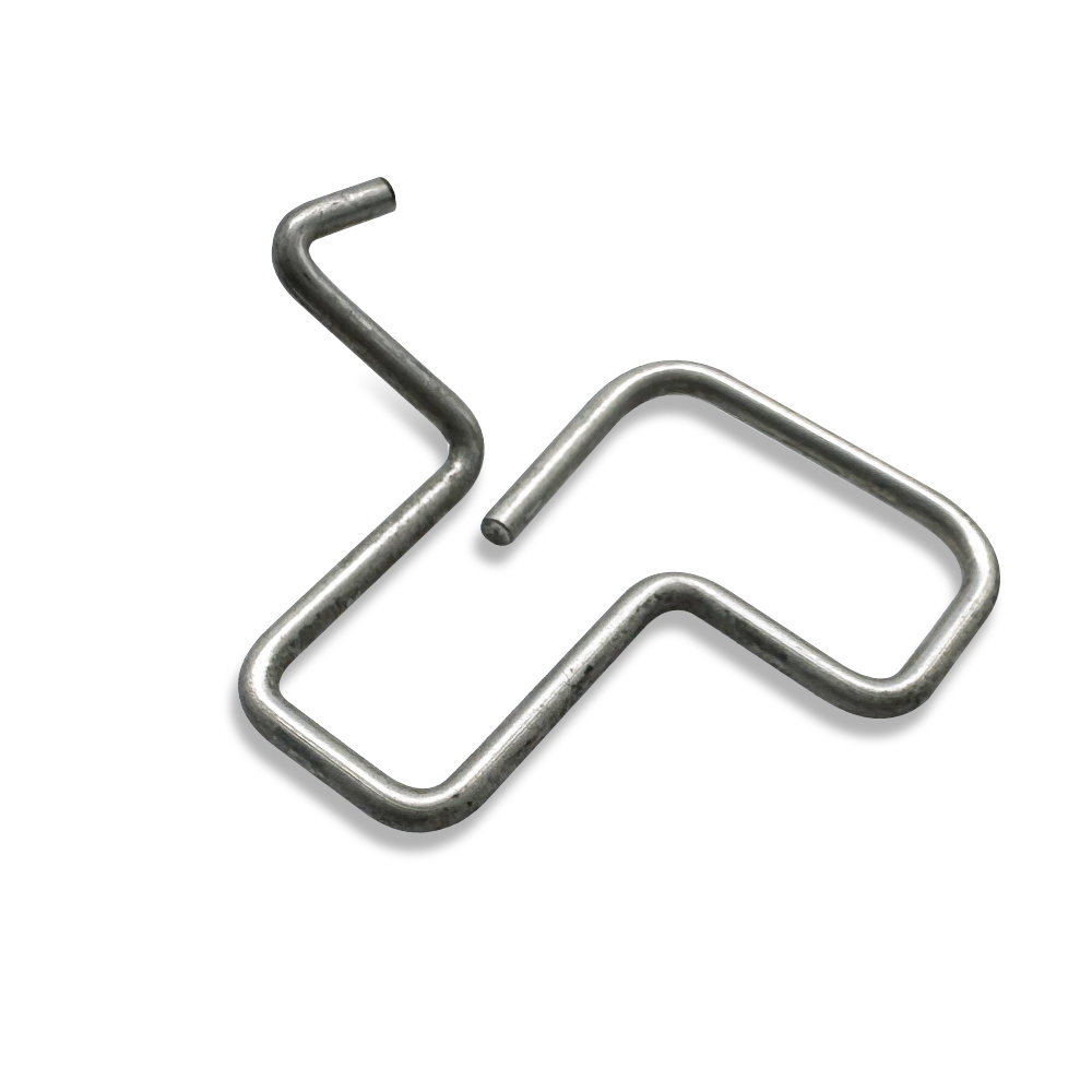
Compare a formed wire path with a sheet-metal clip
A wire form uses a bent wire path to create its geometry. A sheet-metal spring clip uses a formed strip or sheet profile. Neither construction is automatically the better choice: installation space, contact geometry, required movement and production requirements guide the comparison.
Our special-shaped bent wire clips provide an example of a multi-bend wire structure. For other geometries, review the Spring Clips & Springs range and supply the assembly requirements rather than requesting a shape match alone.
| Design question | Information to provide | Review focus |
|---|---|---|
| Where does the part sit? | Mating-part drawing, mounting points and available space | Location, clearance and orientation |
| How does it move? | Free position, installed position and movement direction | Assembly path and required deflection |
| What must it resist? | Required forces, directions and operating conditions | Retention requirements and validation method |
| How is it serviced? | Removal method and expected operating cycles | Access and repeat-use acceptance criteria |
Show the installed condition as well as the free shape
A drawing of the loose component describes only one state. Add an assembly view showing where the clip contacts the mating part and how it is supported. Mark the required travel, clearance and any surfaces that must not be scratched or obstructed.
For a component that flexes, distinguish the installation movement from the normal working movement. Define any insertion-force or removal-force requirement together with the measurement position and test setup. A force value without its test condition is not a complete acceptance criterion.
Specify material and surface requirements together
Material and finish should follow the working environment and functional requirements. Provide the specified grade and material condition when already defined. Otherwise, describe the operating conditions and identify which choices remain open for engineering review.
Consider the surfaces that touch the mating part, the required edge or end condition, and any coating restrictions. A visually similar wire diameter or outline does not establish equal spring behavior. Do not approve a replacement solely from a photograph or a nominal outside dimension.
Agree what the sample must demonstrate
Build the sample review around the intended assembly. Confirm fit, installation and removal, contact positions and the specified functional checks. Where repeated movement is required, agree the cycle-test conditions and acceptance criteria before interpreting a sample as suitable for service.
Record the approved drawing revision and any agreed changes to the mating components. Keep dimensional acceptance separate from functional acceptance: a part can match a drawing yet still require evaluation in the complete assembly.
What to send for a project review
- Part and assembly drawings, including the current revision.
- Free and installed positions, mating geometry and available space.
- Required retention, movement and installation conditions.
- Material, finish, contact-surface and end-condition requirements.
- Sample and production quantities, test requirements and requested schedule.
See our manufacturing services for the project workflow. If a requirement is still being developed, distinguish it from the dimensions and conditions already fixed in the design.
Frequently asked questions
Can one wire clip replace several similar-looking versions?
Only after the differences and each assembly’s requirements have been reviewed. Similar outlines may conceal different contact positions, material conditions or working movements. Provide the individual drawings and intended uses for comparison.
Can a physical sample replace an assembly drawing?
A sample helps explain the component, but it may not reveal its installed position, original requirements or wear history. Supply the mating-part information and functional expectations with it.
Should a clip be used as an electrical contact?
Do not infer electrical-contact suitability from a metal retaining function. Electrical requirements, contact surfaces and validation must be specified separately for an electrical-contact application.
Related Products
Discuss your component requirements
For custom parts, share drawings, material requirements and quantities. For standard fasteners, include the part number, specifications and installation conditions.



