
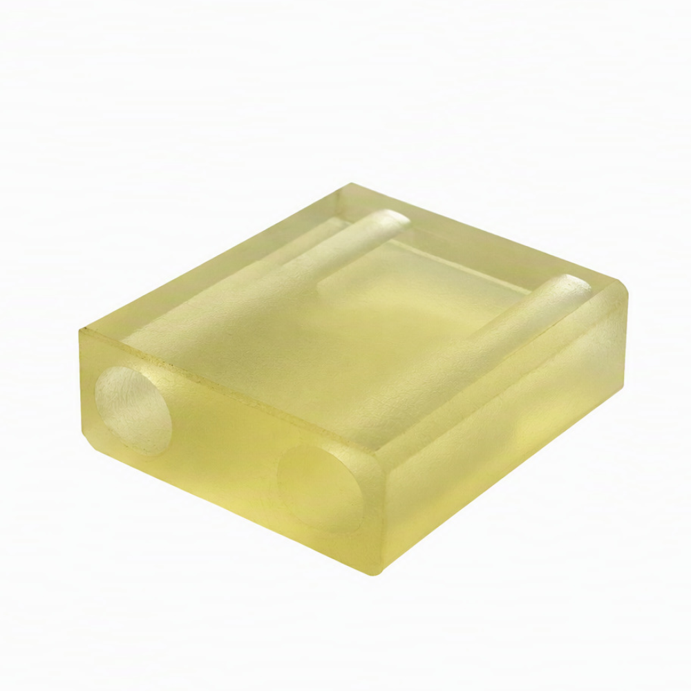
Custom Machined Plastic Parts with Grooves and Side Holes
- Part No :
-
Product Type: Custom Machined Plastic Component
Manufacturing Process: CNC Turning; Secondary Milling and Drilling as Required by Drawing
Material: Engineering Plastic; Exact Grade to Be Confirmed
Visible Structure: Rectangular Block with Parallel Top Grooves and Side Holes
Dimensions: Customized to Customer Drawing or Sample
Groove Requirements: Width, Depth, Spacing and Profile as Specified
Hole Requirements: Diameter, Position, Depth and Fit as Specified
Tolerance: According to Approved Drawing
Surface Condition: As Machined unless Otherwise Specified
Production Type: Made to Order
Quotation Basis: Drawing, Material Grade, Quantity, Tolerances and Inspection Requirements - Inquiry now
Detailed description
Custom Machined Plastic Parts with Grooves and Side Holes
This made-to-order engineering plastic component has a rectangular body, two parallel grooves or guide features on the top face, and circular holes on the side. The photographed sample has a translucent yellow-green appearance, but the exact plastic type and grade must be confirmed from the drawing, material specification or physical sample before production.
Dimensions, groove geometry, hole sizes, hole positions, edge radii, tolerances and surface requirements are controlled by the approved customer drawing. Because this is a custom component, no fixed standard dimensions apply.
Typical Manufacturing Process
1. Drawing and Material Review
The drawing, application conditions and required material properties are reviewed. The plastic grade, stock form, dimensional stability and inspection requirements are confirmed before machining.
2. Blank Preparation
Plastic stock is cut with suitable machining allowance. The blank is checked for sufficient size, surface condition and material identification.
3. CNC Turning
Where specified by the process plan, turning is used to produce circular reference features, bores, shoulders or other rotational geometry. Workholding and cutting conditions are selected to reduce deformation and heat buildup.
4. Secondary Milling and Groove Machining
The rectangular profile, recessed top surface and parallel grooves are typically produced by milling when required by the approved drawing. Groove width, depth, spacing and parallelism are controlled from consistent datums.
5. Drilling or Boring
Side holes are machined to the specified diameter, position, depth and fit. Hole breakout, wall thickness and the relationship between the holes and top features require particular attention.
6. Deburring and Cleaning
Edges, grooves and hole openings are deburred without excessively rounding functional surfaces. Plastic chips and residues are removed while protecting the visible finish.
7. Final Inspection
Inspection items are defined by the approved drawing and may include overall dimensions, groove geometry, hole size and position, feature alignment, flatness and surface condition.
Key Manufacturing Considerations
The exact material grade must be confirmed because different engineering plastics respond differently to cutting heat, moisture and clamping pressure. Excessive clamping may deform the block, while unsuitable cutting conditions may cause heat buildup, dimensional changes or poor edges.
The spacing, depth, profile and parallelism of the two top grooves should be clearly defined. The side holes must share a consistent datum system with the upper features, with attention to hole position, burrs and possible wall deformation.
Information Required for Quotation
Please provide a 2D or 3D drawing, or a physical sample, together with the exact plastic grade, dimensions, groove and hole requirements, tolerances, order quantity, application conditions and inspection requirements.



