
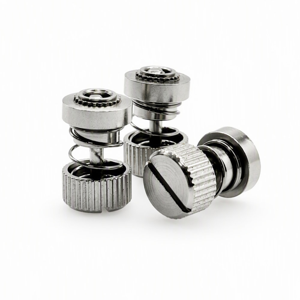
PF31-M3-16 Captive Panel Screw, Spring-Loaded
- Part No : PF31-M3-16
-
- Product No.: PF31-M3-16
- Type: Spring-loaded captive panel screw
- Installation: Self-clinching
- Thread: M3 x 0.5
- Catalog Screw Length: 16 mm
- Drive: Slotted
- Mounting Hole: 5.50 mm
- Minimum Panel Thickness: 1.00 mm
- A: 0.92 mm
- C Max.: 5.48 mm
- E: 10.31 ±0.25 mm
- G: 7.62 ±0.40 mm
- H: 5.13 ±0.13 mm
- T1 Nom.: 8.26 mm
- T2 Nom.: 15.11 mm
- Minimum Edge Distance: 6.60 mm
Catalog reference dimensions; verify the approved drawing or sample before production.
- Inquiry now
Detailed description
Product Overview
The PF31-M3-16 captive panel screw combines an M3 x 0.5 thread with a slotted knurled head and an exposed spring. This self-clinching assembly retains the screw on a removable panel, helping keep the fastening components together during access and servicing.
The spring-loaded arrangement provides distinct compressed and released positions. Allow space for the released assembly as well as access to the slot and knurled head. The LAMBOOR catalog identifies 16 mm as the selected screw length for this part; that value is not the same as the drawing’s G dimension.
Catalog Dimensions and Panel Requirements
Values below follow the PF30/31/32 page of the LAMBOOR Standard Fastener Catalog V0.1, metric PF31 M3 entry with the 16 mm screw-length selection. All dimensions are in millimeters. The catalog describes its data as manually measured reference values, with the actual product taking precedence. Confirm the approved drawing or sample for production acceptance.
| Specification | Value |
|---|---|
| Product number | PF31-M3-16 |
| Thread size and pitch | M3 x 0.5 |
| Catalog screw length | 16 mm |
| Drive style | Slotted |
| Installation | Self-clinching |
| Mounting hole | 5.50 mm |
| Minimum panel thickness | 1.00 mm |
| A | 0.92 mm |
| C, maximum | 5.48 mm |
| E | 10.31 ±0.25 mm |
| G | 7.62 ±0.40 mm |
| H | 5.13 ±0.13 mm |
| T1, nominal | 8.26 mm |
| T2, nominal | 15.11 mm |
| Minimum edge distance | 6.60 mm |
Part Number, Materials and Selection
PF31 is the product series and M3 is the thread code. The final 16 corresponds to the 16 mm selection in the metric screw-length column. That column also lists 20 mm for M3. Use the drawing to distinguish screw length from projection and assembly height; the catalog’s designation example uses a different suffix and should not replace this part number.
The family page lists two material configurations: a nickel-plated steel retainer with a stainless steel spring, and an all-stainless-steel version. Specify the required configuration when ordering. Do not infer that every component is nickel-plated or that the pictured silver assembly is all stainless steel. Any required alloy grade, coating thickness or corrosion test should be defined in the order documentation.
Installation and Clearance Review
Use the PF31 mounting arrangement and review the 5.50 mm hole, 1.00 mm minimum panel thickness and 6.60 mm minimum edge distance together. Panel material, hardness and installation tooling must suit the approved assembly. This catalog row does not specify numerical installation-force or sheet-hardness limits.
Check the compressed and released positions shown in the catalog drawing. T1 and T2 are nominal assembly dimensions, not permissible spring travel or a spring-force specification. Verify seating, free movement, thread engagement and screwdriver clearance with the mating components before production. Avoid transferring installation instructions from a flare-mounted captive-screw family.
Frequently Asked Questions
Does the 16 mm selection provide 16 mm of thread projection?
No. The table separates screw length from G. It lists 16 and 20 mm screw-length selections for M3 while showing G as 7.62 ±0.40 mm in the shared M3 dimensional entry. Do not calculate engagement from the suffix alone. Check the exact selected assembly drawing and mating-panel stack before ordering.
Can PF32-M3 replace PF31-M3-16 on a 1 mm panel?
Not under the catalog’s minimum-thickness requirement. The PF32 M3 entry requires at least 1.40 mm panel thickness and lists A = 1.38 mm, whereas PF31 lists 1.00 mm and A = 0.92 mm. Review both the series and screw-length selection rather than choosing only by the M3 thread.
Can the required spring force be calculated from T1 and T2?
No. Those nominal dimensions describe the illustrated assembly positions; they do not provide spring rate, preload or a load-deflection curve. If release force or spring performance matters to the application, include that requirement in the inquiry and verify it against approved technical data or sample testing.
Request a Quote
Send PF31-M3-16, quantity, material configuration, panel material and thickness, and the mating-thread details. Include any spring-performance, finish or inspection requirements. Request current price, availability, minimum order quantity and lead time with the quotation.



