Custom Stamping Parts & Assembly For Card Dispenser
- Part No :
-
Custom Stamping Parts & Assembly For Card Dispenser product parameters
The specifications below describe this stamping and assembly case. Define component-specific requirements in the drawing and BOM for your project.
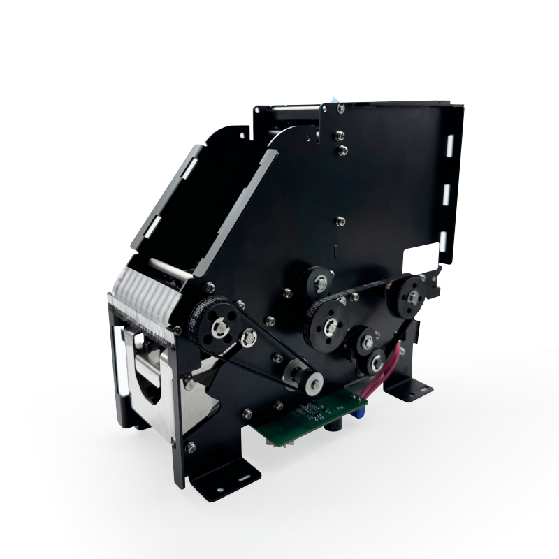
Application Highway card dispenser case Manufacturing process Metal stamping and assembly Case material SUS304; assign materials by component in the project BOM Case surface treatment Powder coating for the case metalwork; finish and masking per component drawing Visible structure Formed frames, mounting feet and front guide area with a belt-and-pulley mechanism Dimensions and interfaces Units, sheet thickness, mounting datums and mating dimensions per approved drawing Assembly scope Define manufactured, assembled and customer-supplied components in the BOM Acceptance requirements Drawing-based dimensional checks; any functional test by agreed method and criteria - Inquiry now
Detailed description
Custom Stamping Parts & Assembly For Card Dispenser
Highway Card Dispenser Stamping and Assembly Case
This highway card dispenser example combines metal stamping with assembly. The photographed structure includes formed side frames, mounting feet and a front guide area alongside a belt-and-pulley mechanism and a circuit board. The case specification identifies SUS304 and powder coating for the metalwork. Specify the material and finish of each component in the project drawing and bill of materials (BOM); these case details do not define the belts, pulleys, shafts, fasteners or electronics.
Define the Metal Parts and Assembly Scope
Use component drawings to define sheet thickness, formed edges, holes, mounting features and the required finish. Use an assembly drawing to show how the stamped parts locate the card path and connect to the surrounding equipment. Identify which components LAMBOOR is to manufacture, which are to be assembled, and which will be supplied by the customer.
Drawing and Inspection Priorities
Define the mounting datums, guide alignment, shaft-support locations and mating clearances that matter to your design. Include units, tolerances and inspection criteria for these interfaces. Review burr requirements at card-contact edges and the effect of coating buildup on mating or locating surfaces. State which checks apply before coating and which apply to the finished assembly.
Request a Project Review
Send the component and assembly drawing revisions, BOM, order quantity and required delivery date. Include the card-path layout, equipment mounting interfaces, component supply responsibilities and acceptance requirements. Confirm the manufacturing and assembly scope for your project before ordering.
Frequently Asked Questions
Can the assembly use customer-supplied drive and control components?
Identify customer-supplied items separately in the BOM and assembly drawing. Include their part numbers, mounting details and interface drawings, and state who supplies and installs each item. A visible belt drive or circuit board in the example does not establish compatibility with your motor, sensor or controller; review the proposed components together with the metal-part drawings.
How should powder coating be specified near mating surfaces?
Mark the surfaces to be coated and any areas requiring masking on each component drawing. State the finish and appearance requirements, and define whether mating dimensions are accepted before or after coating. Pay particular attention to locating holes, shaft supports and card-guide interfaces, where coating buildup can affect fit. Specify the finish separately for components outside the case metalwork.
What information is needed for assembly acceptance?
Provide the dimensional inspection points and acceptance criteria, then define any functional test separately. For a card-path test, identify the representative cards, drive and control setup, test conditions and required result. Agree the test method and who supplies the test components before ordering. The photograph does not establish card compatibility, throughput, continuous-operation performance or an anti-jamming result.
About our company
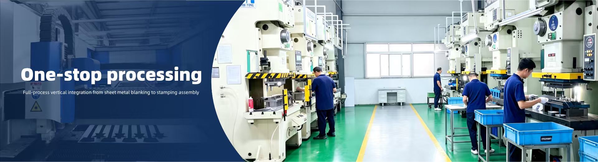
Dongguan Lanbo Electronic Technology Co., Ltd. (Brand: LAMBOOR) was established in 2010 with 15 years of experience in precision hardware manufacturing. We own a 3,000 sq.m standardized factory and employ over 100 professional technicians, acting as an integrated one-stop manufacturer specializing in custom precision hardware structural components, covering mold development, stamping, sheet metal, CNC turning, welding and dust-free assembly.
We are fully equipped with Jinfeng/Aomate stamping machines, laser cutting machines, CNC bending machines, together with complete QC testing equipment including 2D projectors, salt spray testers and tensile testers. Certified to ISO9001:2015, we hold multiple utility model patents for hardware molds.
Our products are widely applied in consumer electronics, optical communication, medical devices, automotive and new energy electrical industries, with more than 400 customized projects completed. We maintain long-term partnerships with renowned enterprises including KYOCERA, Foxconn and RICOH.
63% of our annual RMB 30 million revenue comes from overseas exports. Our self-developed progressive mold technology cuts processing costs by 80%. We support rapid prototyping and mass production, delivering stable, cost-effective customized hardware solutions for global clients.
contact us
Dongguan Lanbo Electronics Technology Co., Ltd.
- Site: http://www.lamboor.com
- Add: 2nd Floor, No.6 Gaoke Industry 5th Road, 4th Village,Tangxia Town, Dongguan, Guangdong, China (Mainland)
- Tel: 86-0769-88004528
- Phone: 86-13559772755
 Lily lily@lamboor.com +86-13559772755
- Catherine sales@lamboor.com +86-18928215298
- Wisdom sales01@lamboor.com +86-18929157606