
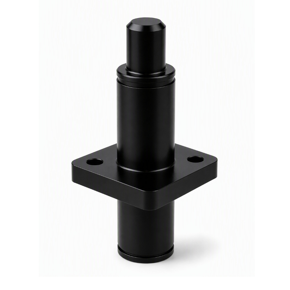
Custom Flanged Shaft with Square Mounting Plate and Grooves
- Part No :
-
- Product Type: Custom Flanged Shaft
- Manufacturing Process: CNC Turning
- Structure: Stepped Cylindrical Body, Square Mounting Plate, Mounting Holes and Circumferential Grooves
- Material Options: Carbon or Alloy Steel, Stainless Steel or Aluminum Alloy
- Surface Finish Options: Material-Compatible Machined, Black-Oxide, Plated, Passivated or Anodized Finishes
- Diameters, Plate and Hole Pattern: Customized to Drawing
- Groove Profile and Position: According to Drawing Requirements
- Tolerances and Inspection: According to Drawing Requirements
- Production Type: Made to Order
- Quotation Inputs: Drawing, Material, Finish, Mating Interfaces, Critical Tolerances and Quantity
- Inquiry now
Detailed description
This custom flanged shaft has a stepped cylindrical body, a square mounting plate with visible mounting holes, and circumferential grooves near its ends. LAMBOOR supplies drawing-based turned components with the shaft profile, flange interfaces and finish selected for the assembly. It is a made-to-order part, not a standard shaft defined by one catalog dimension set.
Typical Manufacturing Route
A typical route begins with drawing review, blank selection and establishment of reference faces. Turning forms the cylindrical steps, end profiles and circumferential grooves. The square plate outline and mounting-hole requirements are incorporated into the manufacturing plan according to the approved design and blank. The exact operation sequence is chosen to preserve the relationship between the shaft axis and mounting face. Edge finishing, cleaning, specified treatment and inspection complete the route.
Machining and Interface Priorities
- Shaft-to-flange relationship: Define the locating axis, mounting face and relevant perpendicularity or position requirements.
- Mounting pattern: Dimension the hole locations from functional datums rather than an unspecified visual center.
- Stepped ends: State mating fits, usable lengths and transition clearances for each cylindrical section.
- Grooves: Define width, depth, root radius, edge condition and axial position. Their function must come from the assembly requirements.
- Finish-protected interfaces: Identify which mounting faces and fits require masking or coating allowance.
Material and Finish Selection
Carbon and alloy steels are options where strength or wear requirements dominate. Stainless steel may be selected for corrosion-focused designs, while aluminum alloys can reduce weight. Grade, condition and any heat treatment should be selected against the actual loading, environment and mating materials.
Compatible options include an as-machined finish, black oxide or suitable plating on steel, passivation on stainless steel, and anodizing on aluminum. Black oxide needs appropriate supplementary corrosion protection and is not equivalent to a thick barrier coating. Plating high-strength steel may require hydrogen-embrittlement control. Specify coating allowance on cylindrical fits and groove features; thick powder coating should not be used on unmasked precision locating faces. For an appearance-controlled part, define color, texture and a reference acceptance method separately from functional requirements.
Customization and Inspection
The drawing controls shaft diameters, step lengths, flange thickness and outline, hole pattern, grooves and edge treatment. Inspection planning should address the shaft axis relative to the mounting plane, the functional hole pattern, groove geometry and post-finish mating dimensions. Add first-article or report requirements when needed; no universal tolerance or load rating is implied.
FAQ
Can a bearing or retaining ring be selected from the shaft photograph?
No. The cylindrical steps and grooves do not establish a bearing fit or retaining-ring standard. Provide the intended mating component and its interface requirements, including groove geometry and allowable clearances. Compatibility must be checked against those dimensions; a visually similar groove is not evidence of an interchangeable ring seat.
Are the flange bolts necessarily the locating features?
Not necessarily. Bolts may clamp the plate while a shaft diameter, pilot or other feature locates the assembly. Identify the actual locating scheme on the drawing and distinguish clearance holes from fitted locating holes. This determines which positions and face relationships need functional control.
How should a uniform dark appearance be approved?
Use an agreed finish specification and appearance reference rather than the photograph alone. Define visible surfaces, permissible color or texture variation and any contact marks that are acceptable. Match the finish to the chosen metal and service environment, with separate dimensional checks for coated mating surfaces.
Request a Drawing-Based Quotation
Send the 2D drawing and available 3D model, material grade, finish, quantity and inspection requirements. Highlight the shaft fits, mounting datums, intended groove interfaces and any first-article or packaging conditions.



