
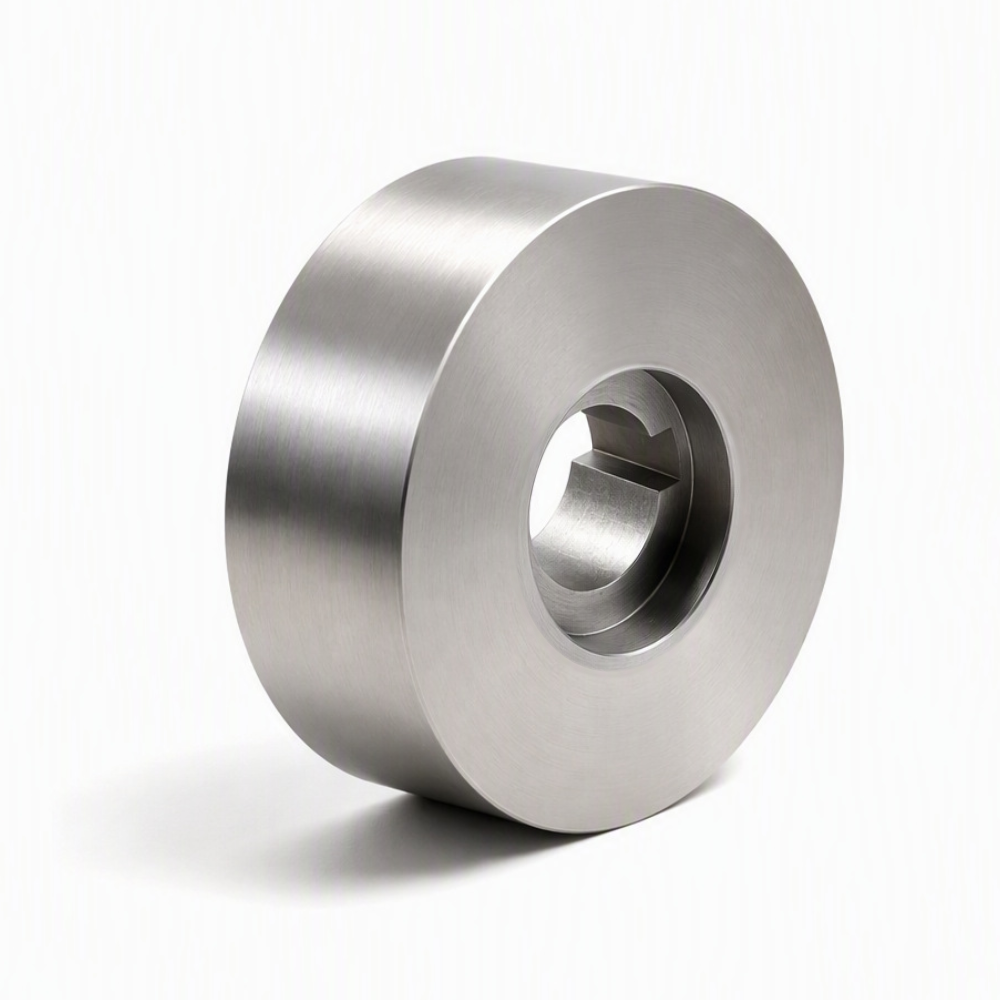
Custom CNC Turned Disc with Stepped Bore and Internal Slot
- Part No :
-
Product Type Custom Turned Disc Manufacturing Process Turning; Additional Features to Drawing Structure Circular Body, Stepped Central Bore and Internal Slot Material Options Aluminum Alloys, Stainless Steel, Carbon or Alloy Steel, Brass Dimensions Outside Diameter, Thickness, Bore Steps and Slot Geometry Customized to Drawing Fits and Tolerances According to Approved Drawing and Mating Requirements Surface Finish Options As Machined; Material-Compatible Finishes to Specification Production Type Made to Order Quotation Inputs Drawing or Sample, Material, Quantity and Inspection Requirements - Inquiry now
Detailed description
Custom Turned Disc with Drawing-Controlled Bore Features
This custom CNC turned disc combines a broad circular body with a stepped central bore and an internal slot. The outside diameter, disc thickness, bore diameters, recess depth and slot geometry are defined by the customer drawing. It is a made-to-order metal component, rather than a catalog part with fixed dimensions or a predetermined application.
Typical Manufacturing Route
A typical route starts with a suitable blank and machining allowance for the selected material. Facing and outside-diameter turning establish the principal circular surfaces. Boring creates the central opening and its internal steps. Subsequent setups complete the opposite face and drawing-specified details. The internal slot requires a separately planned feature operation appropriate to its geometry; its presence does not establish a particular slot-cutting method.
Deburring and cleaning follow machining, with particular attention to the intersections between the slot and bore. Any specified surface treatment is coordinated with the finishing allowance. Inspection is then performed against the approved drawing and agreed acceptance criteria. This is a typical process outline, not a production record for the pictured component.
Bore, Face and Slot Control
The drawing should identify which bore surface and face establish the functional datums. Relevant controls may include bore size and form, the relationship between bore steps, face flatness, face runout and perpendicularity. Specify only those controls needed by the mating assembly; a circular appearance alone does not establish a precision fit or a balance requirement.
Slot width, depth, axial extent, corner form and location relative to the bore must be defined independently. Edge breaks should remove burrs without changing a mating edge or enlarging a controlled slot. Workholding should protect finished faces and avoid distortion when the chosen dimensions leave a narrow section around the bore.
Material and Surface Finish Selection
Material options can include aluminum alloys, stainless steel, carbon or alloy steel, and brass. Select the grade according to the required strength, weight, corrosion resistance, wear conditions and cost. The selected material and any heat-treatment condition belong on the drawing or purchase specification.
As-machined surfaces are an option. Aluminum may be anodized; stainless steel may be passivated; steel may receive zinc or electroless nickel plating where appropriate. Finishes must suit the chosen material and operating conditions. Anodizing and plating alter dimensions, so bore fits and slot clearances need allowance or masking as specified. Do not apply an uncontrolled coating to a precision mating surface. Plating high-strength steel also requires an agreed hydrogen-embrittlement control specification.
Drawing-Based Inspection
Define the acceptance requirements for outside diameter, thickness, each bore step, recess depth and slot geometry. Add datum-based geometric tolerances and surface roughness only where required. Inspection should address burrs, edge condition and the effect of any final finish on the mating dimensions. Required first-article records, measurement reports or material documents should be stated in the RFQ; no particular result or inspection capability is implied by the image.
FAQ
Can this disc be specified as a rotating component?
Only when the assembly requirements are supplied. The disc shape does not define its operating speed or balance requirement. If the design rotates, include speed, mounting conditions and any applicable balance acceptance specification for engineering review before ordering.
Can a sample replace the drawing for the internal slot?
A sample can support a quotation, but it does not uniquely define the slot’s functional limits. Provide the mating-part geometry or approved dimensions, including clearance, corner form and usable engagement length. Record those requirements in an approved drawing before production.
How should the finished bore be protected during shipment?
Specify protection that matches the bore’s acceptance criteria. Where marking or corrosion could affect assembly, request separation of parts, clean protective wrapping or compatible corrosion protection as appropriate to the material. State restrictions on residues and contact with the controlled surfaces.
Request a Drawing-Based Quotation
Send a 2D drawing and, where available, a 3D model or sample. Include the material grade, outside diameter, thickness, bore steps, slot details, mating requirements, tolerances, surface finish, quantity and inspection documentation. LAMBOOR can review the custom-part requirements as the basis for a quotation.



