
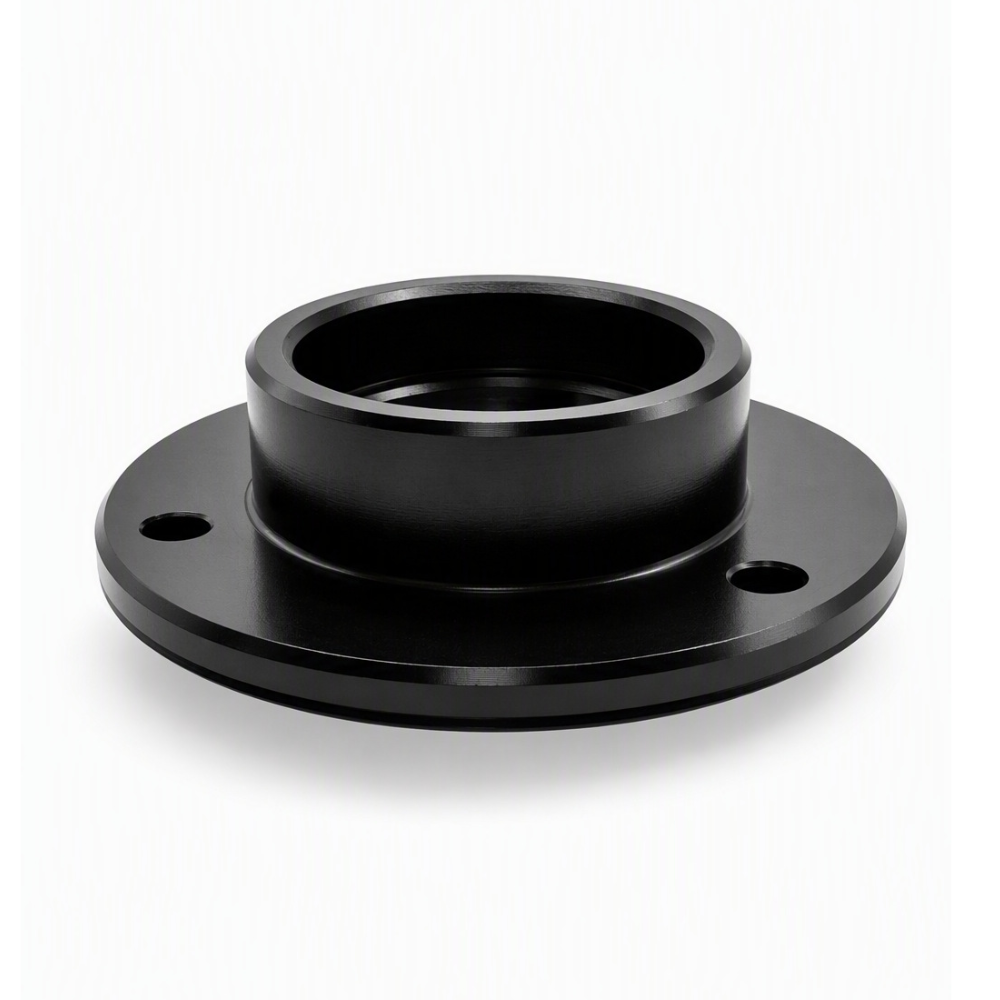
Custom CNC Turned Component with Bore and Circular Flange
- Part No :
-
Item Customization Details Product Type Custom flanged component with bore Manufacturing Process CNC turning; additional hole operations according to the drawing Key Structure Circular flange, raised cylindrical section, axial opening and flange holes Material Options Aluminum alloys, stainless steels, carbon or alloy steels and brass, selected for the project Dimensions Flange diameter and thickness, cylinder height, bore profile and hole layout customized to drawing Fit and Geometry Bore fit, flange face requirements and geometric tolerances according to drawing requirements Hole Requirements Hole count, diameter, spacing and any thread or recess details specified on the drawing Surface Finish Options As machined or a material-compatible finish; precision surfaces and masking defined before processing Quotation Inputs 2D/3D drawings, material grade, finish, quantities and inspection requirements - Inquiry now
Detailed description
Custom Flanged Component with an Axial Bore
This custom CNC turned component combines a circular flange with a raised cylindrical section, an axial opening and holes in the flange. The bore and flange create related internal, external and face features that need to be defined together on the engineering drawing. LAMBOOR supplies drawing-based custom metal parts; dimensions, material grade and finish are selected for the individual project rather than treated as a fixed catalogue specification.
Typical Manufacturing Sequence
A typical route starts with material and blank selection, followed by facing and establishing a turning datum. Rough turning and boring create the flange, cylindrical section and internal profile. Finishing operations establish the specified diameters, face locations and edge details. Flange holes are then produced using a suitable setup referenced to the drawing datums. Deburring, cleaning, any specified surface treatment and final inspection complete the route. The approved drawing and order requirements determine the final sequence.
Bore, Flange Face and Hole Relationships
The bore diameter alone does not describe the complete interface. Specify any internal shoulder, its depth, corner radius and mating clearance in a section view. Where alignment matters, define the relationship between the bore axis, raised outside diameter and flange face through appropriate drawing tolerances. An unrestricted corner radius at the cylinder-to-flange transition may interfere with a mating part, so the required clearance should be part of the design review.
Workholding deserves attention because concentrated clamping force can affect the bore or leave marks on the flange. The setup should support the component without distorting the finished faces. Hole positioning needs a defined reference to the bore and any angular orientation feature, not just a hole diameter. Burr removal at hole exits and bore edges should preserve specified edge breaks and mating surfaces.
Material and Compatible Finish Options
Aluminum alloys may suit weight-sensitive designs; stainless steels may suit corrosion-related requirements. Carbon or alloy steels can be considered where strength or wear requirements drive selection, while brass may suit particular machining, conductivity or interface needs. The grade, condition and service environment should be agreed for the project before a compatible finish is selected.
Aluminum options include anodizing or hard anodizing, with dimensional allowance on the bore and outside fits. Stainless steel options include passivation or electropolishing. Steel options include zinc or electroless nickel plating, black oxide and compatible coatings; black oxide alone should not be treated as substantial corrosion protection. Specify hydrogen-embrittlement controls when relevant to plated high-strength steel. Mask precision surfaces when using powder coating, and define coating coverage around holes and internal shoulders before manufacture.
Drawing-Based Inspection and Ordering
The inspection plan should identify the flange diameter and thickness, cylinder height, bore profile, hole locations and the geometric relationships that affect assembly. Define acceptance limits, surface roughness requirements and the reporting scope on the drawing or purchase specification. Requirements that apply after finishing should be distinguished from intermediate machining checks. Packaging should protect bore edges and flange faces against handling damage.
FAQ
Is this an interchangeable standard pipe flange?
No standard-interface interchangeability is specified for this custom component. A circular flange and bore do not establish a pipe standard, pressure rating or sealing arrangement. If an existing interface must be matched, provide its controlled dimensions and applicable requirements for engineering review before ordering.
Can the flange holes include threads or fastener recesses?
Such features can be evaluated as drawing-based variants rather than assumed from this image. Define the thread specification, engagement depth or recess dimensions, together with flange thickness and edge distances. Supply the mating fastener information so available material and tool access can be reviewed.
How should a dark appearance be approved for repeat orders?
Use a specified finish and an agreed appearance reference, not the photograph alone. Define visible surfaces, acceptable variation and any areas excluded from treatment. Material and finish compatibility must also be considered; approve the appearance criteria together with dimensional acceptance requirements before production.
Request a Drawing-Based Quote
Send the 2D drawing and available 3D model, material grade, bore and flange details, hole pattern, finish specification, quantities and required inspection documentation. Include the mating interface drawing where assembly relationships are critical. Contact LAMBOOR about this custom turned component.



