
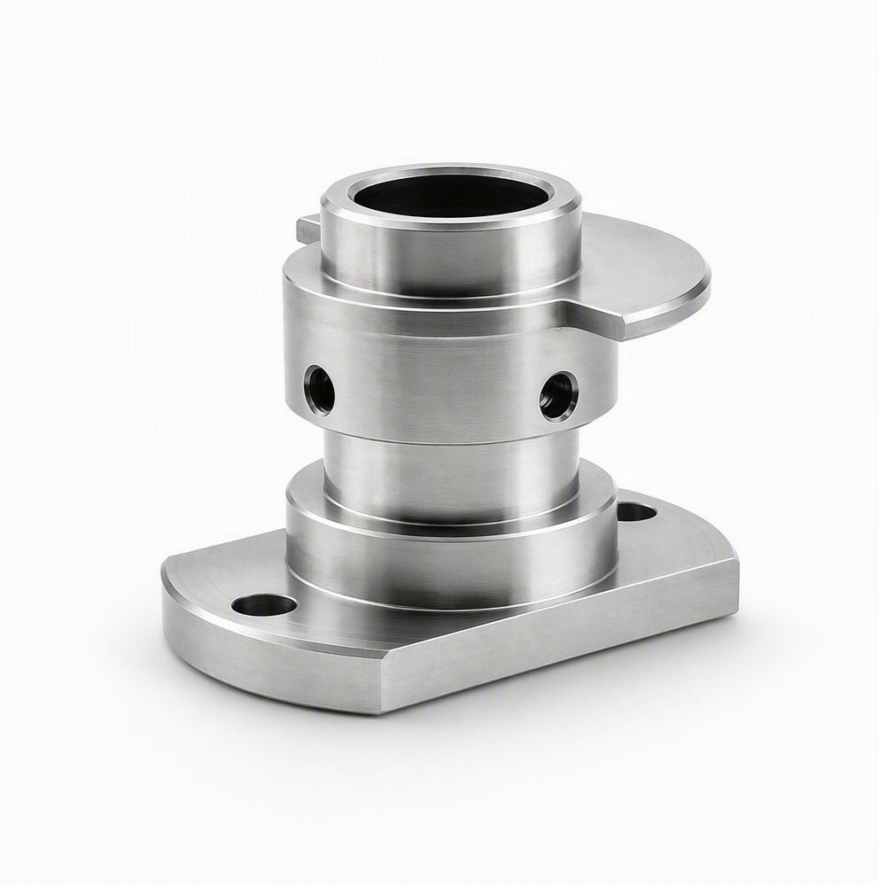
Custom Machined Housing with Flanges and Radial Holes
- Part No :
-
- Product Type: Custom Machined Housing
- Manufacturing Process: CNC Turning and Milling
- Structure: Stepped Cylindrical Body, Axial Opening, Flanged Sections and Radial Holes
- Material Options: Aluminum Alloy, Stainless Steel, Carbon or Alloy Steel, or Brass
- Bore and Flange Geometry: Customized to Drawing
- Hole and Thread Requirements: According to Drawing
- Tolerances and Inspection: According to Drawing Requirements
- Surface Finish Options: Material-Compatible Machined, Anodized, Passivated or Plated Finishes
- Production Type: Made to Order
- Quotation Inputs: Drawing, Material Grade, Mating Geometry, Finish, Quantity and Inspection Requirements
- Inquiry now
Detailed description
This custom machined housing combines a stepped cylindrical body, a visible axial opening, flanged sections and radial holes. The lower flange has two visible mounting openings, while the upper flange has an asymmetric outline. LAMBOOR supplies this non-standard component through CNC turning and milling to customer drawings, with the internal geometry and mounting relationships defined for the intended assembly.
Typical Turning and Milling Route
A typical route starts with drawing review and preparation of a suitable blank. Facing, external turning and internal machining establish the main axis and stepped circular surfaces. Milling creates the non-circular flange boundaries, while drilling and thread machining address the specified mounting and radial-hole features. The plan must retain common references between the turned body and milled features. Deburring, cleaning, compatible surface treatment and final inspection complete the route.
Key Manufacturing Priorities
- Bore and locating steps: Specify the relationship between the axial interface, outside diameters and shoulder faces. Geometric requirements must refer to the functional assembly datums.
- Flange orientation: Control the angular relationship between the asymmetric upper profile, lower mounting holes and radial holes. Independent size checks do not establish correct orientation.
- Radial threads: Define thread designation, depth, entry treatment and any intersection with the internal cavity. Remove internal burrs without damaging the thread or adjacent wall.
- Workholding: Support the stepped body and projecting flange sections to limit distortion and protect finished contact surfaces.
Material Options
Aluminum alloys are options for weight-sensitive designs; stainless steels for corrosion-focused requirements; carbon or alloy steels for strength, wear or cost considerations; and brass for machinability or specific electrical requirements. Select the actual grade and condition against the service environment and mating materials. The wall remaining between the bore and radial holes, and the material around the flange openings, should be assessed as part of the drawing review.
Compatible Surface Finishes
As-machined surfaces can be retained where appropriate. Aluminum can use anodizing, hard anodizing or bead blasting. Stainless steel can use passivation, brushing or electropolishing. Suitable steels can use plating, phosphating or black oxide; brass can use polishing or nickel plating. Treatment must be compatible with the selected material and service conditions.
Allow for dimensional changes on the bore, locating shoulders and threads, and define masking where fit is critical. Anodized color variation may need an appearance reference. Black oxide requires suitable supplementary corrosion protection, and plating high-strength steel may require hydrogen-embrittlement controls. Thick powder coating is unsuitable for unmasked precision bores or threaded interfaces.
Drawing-Controlled Customization and Inspection
Define the complete bore layout, stepped diameters, flange thicknesses, mounting-hole positions, radial-thread details and corner radii. Specify the functional axis and faces, geometric tolerances, surface roughness and inspection condition after treatment. Include cleanliness and burr requirements at intersecting features, as well as any dimensional-report or first-article requirements. No pressure, sealing or bearing performance follows solely from the shape.
FAQ
Can the radial threaded holes be used as fluid ports?
Only if the design explicitly specifies that function. Threaded openings alone do not establish a sealing system, pressure rating or connection standard. Provide the port specification, internal passage layout, sealing method and validation requirements if fluid service is intended. These requirements must be reviewed before quotation or production.
How should the two flange sections be oriented during assembly?
Define their angular relationship from a shared datum on the assembly drawing. Show the required orientation of the asymmetric projection, lower mounting pattern and radial holes, including clearance to nearby parts. A circular bore can locate the axis but does not by itself establish the required rotational position.
Is the axial opening a through bore or a blind cavity?
The complete drawing determines the bore arrangement. Specify depth, internal steps, end conditions and whether radial holes connect to the cavity. A visible opening does not define the opposite end. Include a section view when needed so mating-part insertion, wall thickness and inspection access can be reviewed accurately.
Request a Quotation
Provide a dimensioned drawing and available 3D model, material grade, surface finish, quantity and inspection requirements. Include a section view of the internal geometry, mating interfaces, flange orientation and complete thread specifications. State any sample approval, cleanliness or packaging requirements.



