
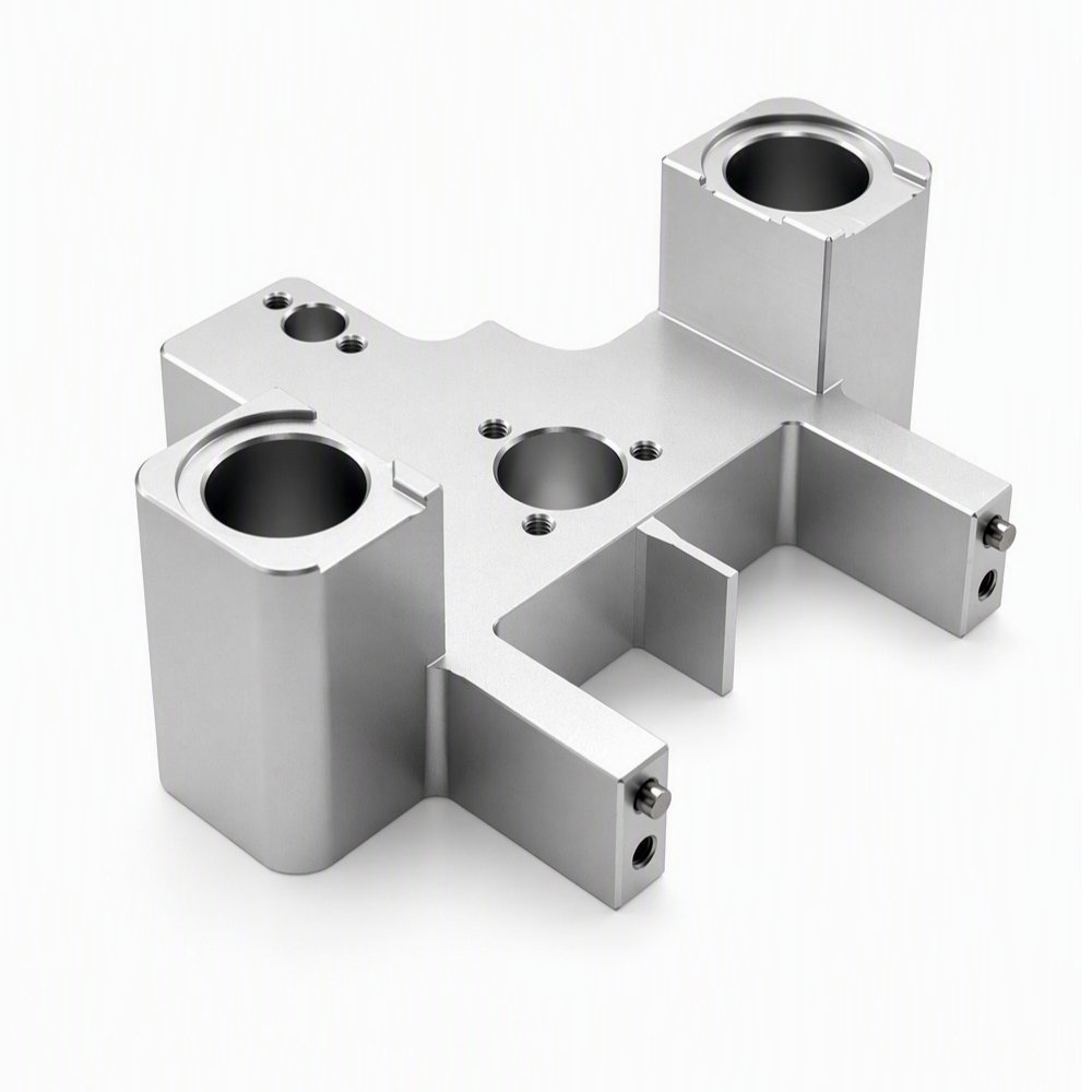
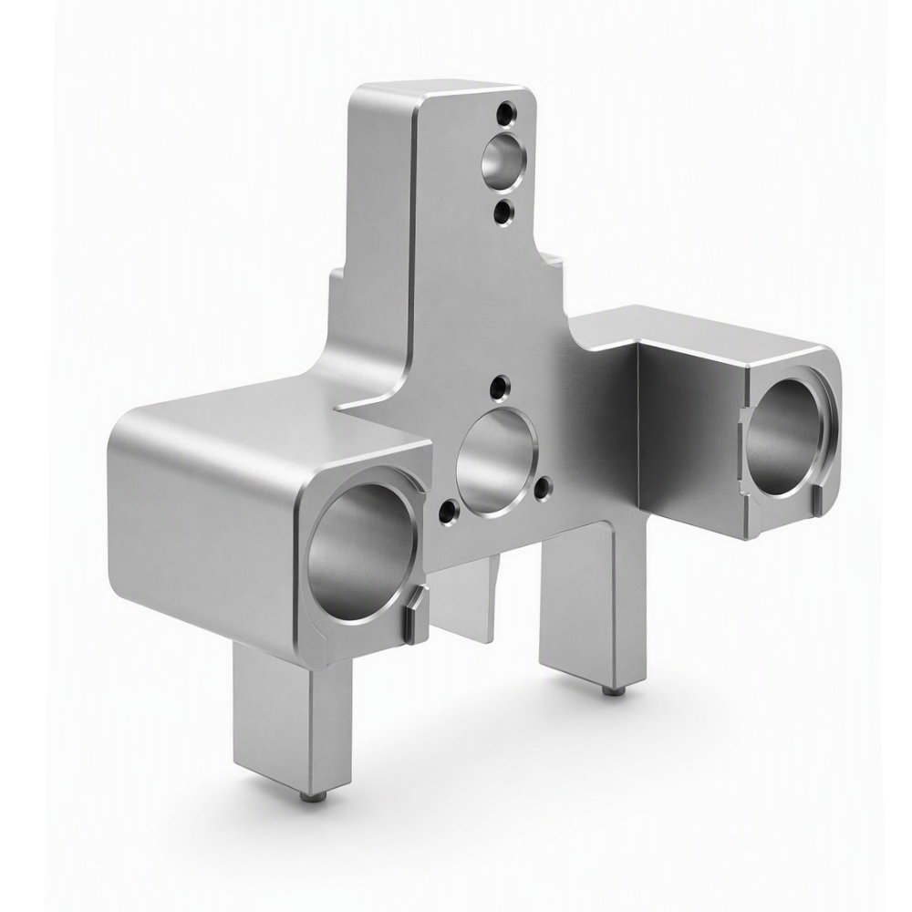
Custom Machined Component for Blood Testing Equipment
- Part No :
-
Product Type: Non-standard custom machined component
Application: Blood testing equipment
Manufacturing Process: Turning and milling; operation sequence according to drawing
Structure: Irregular body, raised bore blocks, circular openings and mounting features
Material Options: Aluminum alloys, stainless steels, carbon/alloy steels or brass, subject to design review
Surface Finish Options: Aluminum anodizing/conversion coating; stainless steel passivation/electropolishing; compatible steel or brass plating; as-machined options
Dimensions and Fits: Customized to Drawing
Holes and Threads: Size, position, depth and specification according to drawing requirements
Tolerance Basis: Approved drawing and agreed inspection plan
Supply Type: Made to order
Quotation Inputs: Drawing/model, quantity, material, finish, critical interfaces and inspection requirements
- Inquiry now
Detailed description
Custom Machined Component for Blood Testing Equipment
This custom machined component is made for blood testing equipment applications. Its irregular body combines two raised blocks with circular bores, a central opening, smaller holes and extended arms. Turning and milling provide the manufacturing basis for a drawing-defined part with both circular and non-circular features. LAMBOOR supplies custom CNC machining parts according to the customer’s approved design rather than a fixed catalog specification.
Product Structure and Drawing-Controlled Interfaces
The component brings several geometric interfaces into one body. The raised side blocks contain large bores with surrounding recessed features, while the connecting section contains additional openings and smaller mounting features. The relationship between these features is important when the part is incorporated into a larger equipment assembly.
The production drawing should identify the functional datums, bore diameters and depths, hole locations, thread specifications, arm geometry and mating surfaces. Fits, perpendicularity, parallelism and positional tolerances should be assigned to the features that actually control assembly. A photograph is not a dimensional reference; each manufactured version follows its approved drawing and revision.
Use in Blood Testing Equipment
The intended application is installation as a custom mechanical component within blood testing equipment. Its bores, mounting features and extended sections provide drawing-defined interfaces to surrounding parts. During equipment integration, the design owner should establish which features locate the component, which receive mating parts and which secure the assembly.
Before installation, check the drawing revision, mating dimensions, orientation and clearance around adjacent mechanisms. Assemble using the specified fasteners, tightening method and fit requirements, without forcing precision interfaces. Where removal is required for equipment servicing, follow the equipment manufacturer’s disassembly and reassembly instructions.
Equipment-level requirements determine cleaning, corrosion protection, lubricant restrictions and any chemical exposure conditions. Any blood or reagent contact, sterilization requirement, electrical role or diagnostic function must be specified by the equipment designer. The final assembly and intended operating conditions require equipment-level validation.
Typical Turning and Milling Route
A typical manufacturing route starts with drawing review, material selection and blank preparation. Circular features are machined through suitable turning or bore-finishing operations, and milling establishes the irregular profile, raised sections, recesses and non-circular details. Drilling and tapping produce the specified hole pattern. The actual operation sequence, fixtures and machine arrangement depend on the drawing and production plan.
Deburring, cleaning, any approved surface treatment and final dimensional inspection follow machining. The combination of turning and milling does not prescribe a particular machine configuration or imply that all features are produced in one setup.
Manufacturing Priorities
- Bore and datum relationships: Preserve the specified locations and orientations of the separated bores relative to the assembly datums.
- Workholding: Support the irregular body without distorting extended arms or marking critical mating surfaces.
- Recesses and transitions: Define tool access, corner radii and remaining wall thickness around bore blocks and cutouts.
- Hole and thread quality: Control hole position, thread depth and burrs at bore intersections according to the drawing.
- Surface condition: Protect finished faces and remove loose chips before inspection and packaging.
Material Options and Selection
Material options include aluminum alloys, stainless steels, carbon or alloy steels and brass, subject to design review. The selected grade is specified for each order. Aluminum may be considered when weight and machining economy matter; stainless steel may be considered for corrosion resistance; steels may be considered for strength or wear requirements; and brass may be considered where its machining or electrical properties suit the design.
Select the grade using loads, assembly weight, environmental exposure, mating materials, cleaning chemicals and cost. Any material certification or traceability requirement should be agreed in the quotation and purchase specification.
Compatible Surface Finish Options
For aluminum, options may include as-machined surfaces, anodizing, hard anodizing, chemical conversion coating or bead blasting. Stainless steel options may include as-machined surfaces, brushing, passivation or electropolishing. Carbon or alloy steels may use zinc plating, electroless nickel plating, black oxide, phosphating or powder coating where compatible. Brass may be supplied as machined, polished, brushed or nickel plated.
Specify coating allowance and masking for bores, threads and datum surfaces before machining. Anodizing can alter fits and appearance; passivation applies to stainless steel; black oxide requires suitable additional corrosion protection; and powder coating should not cover precision mating surfaces unless the design allows its thickness. Plating of high-strength steel requires appropriate hydrogen-embrittlement controls. Finish choice must also account for the equipment’s cleaning and exposure requirements.
Inspection Requirements
An agreed inspection plan should cover critical bore sizes and locations, datum relationships, mounting-hole patterns, specified threads and relevant surface finish. Define acceptance criteria for burrs, cleanliness and treated surfaces. Inspection methods and sampling should be selected to suit the drawing; measurement reports, material documents and finish records can be included when agreed before manufacture. No numerical tolerance or inspection result is implied by this example.
FAQ
Is this component interchangeable between different blood testing equipment models?
No universal interchangeability is implied; this is a drawing-defined custom component, not a model-independent replacement. Similar-looking bores and mounting arms do not establish compatibility. Compare the approved equipment drawing, mating interfaces and available installation space before ordering. The equipment design owner should approve the intended fit and use for each model.
Can a bore size or position be changed while keeping the rest of the component unchanged?
A local change requires a review of the complete component and its mating assembly. Changing one bore can affect the surrounding wall thickness, recessed features, mounting-hole spacing and the relationship between the two raised blocks. Submit a revised drawing with the change identified; unchanged interfaces should remain clearly controlled. Manufacturability and assembly compatibility must be assessed before the revision is accepted.
How should a sample be approved before repeat production?
Agree on sample acceptance criteria before manufacture, then review the sample against the approved drawing revision and intended assembly. For this multi-interface component, the review should address the separated bores, mounting features and clearance around the extended arms. Specify any dimensional report and test-fit requirements in the order. A successful mechanical fit alone does not replace the equipment designer’s required system-level validation.
Request a Drawing-Based Quotation
Send a dimensioned drawing and, where available, a 3D model, with the revision, quantity, material grade, finish, critical fits and inspection requirements. Include the equipment assembly context and any cleaning, chemical exposure, packaging or traceability requirements. These details allow LAMBOOR to review manufacturability and quote the component against a defined specification.



