
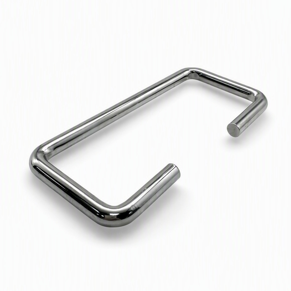
Custom CNC Machined Open-Frame Round Bar
- Part No :
-
Item Specification Product Type Custom open-frame round-profile bar Manufacturing Process Turning and milling; overall profile route according to the approved drawing Structure Open rectangular outline, curved corners and separated inward-facing end sections Material Options Stainless steel, carbon or alloy steel, aluminum alloys and brass, subject to design review Surface Finish Options Brushing or polishing; stainless steel passivation; steel plating; aluminum anodizing, according to material compatibility Profile and Dimensions Round-section size, overall envelope, corner geometry and end spacing customized to drawing End Features End faces, edge breaks and any additional machining according to drawing requirements Tolerance and Inspection Drawing-defined datums, profile, end-position and surface acceptance requirements Supply and Quotation Made to order; provide drawing or sample, material, finish and required quantity - Inquiry now
Detailed description
Custom Open-Frame Round Bar Overview
This custom CNC machined component has a round-profile body arranged in an open rectangular outline. Curved corners connect the longer sections, while two short end sections face inward with a gap between them. The open-frame geometry is the defining feature of this part. LAMBOOR supplies this non-standard component through a drawing-based turning and milling workflow rather than as a fixed catalog item.
The overall profile, cross-section, end positions and surface requirements can be specified for the customer’s design. The product name describes its structure without assigning a particular mounting function or load rating. Suitability for an assembly is determined from the approved drawing and the mating components.
Typical Turning and Milling Workflow
A typical project begins with a review of the profile drawing, material specification and reference datums. Blank preparation and the route used to create the overall outline are selected for the approved design. Turning and milling operations then address the required local features and end geometry, followed by edge finishing, compatible surface treatment and inspection. This is a typical planning sequence, not a claim that the complete curved body is produced in a single turning operation.
Fixturing should support the round sections without marking the specified cosmetic surfaces or changing the end spacing. The open outline also requires a clear relationship between the setup references and the final inspection datums. These decisions should be resolved before production rather than relying on the outside silhouette alone.
Profile and End-Position Control
Drawing priorities for this round-profile component include the overall envelope, corner transitions, relative position of the short ends and the gap between them. If the assembly requires the frame to lie in one plane, that requirement should be defined with a datum and a measurable limit. Local section size and end-face orientation should be specified separately from the overall profile.
Edge breaks at the free ends must preserve any defined contact or locating surfaces. Cosmetic acceptance should distinguish intentional finishing texture from dents, scratches and clamp marks. Where the part meets another component, the mating drawing should establish clearance rather than treating the reference image as a scale drawing.
Material and Surface Finish Selection
Material options may include stainless steel, carbon or alloy steel, aluminum alloys and brass, subject to review of the required geometry and machining route. Selection depends on strength, weight, corrosion exposure, appearance and cost. The specified grade and condition belong on the order drawing.
Compatible finish options include brushing or polishing, passivation for stainless steel, plating for appropriate steels, and anodizing for aluminum. Plating or anodizing allowances should be included where dimensions affect assembly. Precision end features may need masking, and any cosmetic reference should define the finish direction and acceptable variation. Plating high-strength steel requires an appropriate hydrogen-embrittlement control plan.
Drawing-Based Inspection and Quotation
The inspection plan should identify the round-section size, profile envelope, corner geometry, end spacing, end-face condition and any drawing-defined planar relationship. Acceptance criteria and reporting requirements are agreed for the order; this listing does not assign a universal tolerance or inspection result.
For quotation, send a dimensioned drawing or reference sample, material and finish requirements, quantity and the mating-interface information. Highlight the critical datums and cosmetic areas. LAMBOOR can then review the turning and milling requirements together with the complete profile instead of quoting only the visible outline.
Frequently Asked Questions
Does an open-frame shape mean the part is a spring?
No. An open outline alone does not establish elastic behavior or a spring function. If controlled deflection is required, specify the loading direction, allowable movement and validation criteria so the material and design can be reviewed for that requirement.
Can the drawing use centerline dimensions instead of outside dimensions?
Yes, but identify the dimension convention clearly and also specify the round-section size. A centerline envelope and an outside envelope are not interchangeable; the drawing must resolve their relationship at straight sections and curved transitions.
Can the two free ends be changed independently?
Yes, an asymmetric version can be reviewed as a separate drawing configuration. Dimension each end from the selected datums rather than implying symmetry, and provide a distinct drawing revision for quotation and inspection.



