
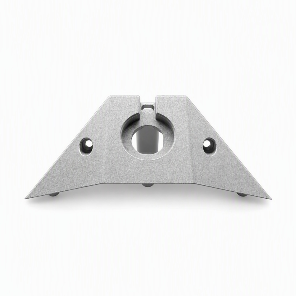
Custom CNC Machined Bracket with Split Bore and Mounting Holes
- Part No :
-
Product Type: Custom Machined Mounting Bracket
Manufacturing Process: CNC Turning and Milling
Material: Specify the material in the drawing or order requirements
Visible Features: Split Central Bore, Internal Key Feature and Two Mounting Holes
Dimensions: Customized to Customer Drawing or Sample
Central Bore: Diameter, Fit and Internal Profile as Specified
Slot Requirements: Width, Depth and Position According to Drawing
Mounting Holes: Size, Position, Depth and Thread Requirements as Specified
Tolerance: According to Approved Drawing
Surface Finish: Specify the required surface condition in the drawing or order requirements
Production Type: Made to Order
Quotation Basis: Drawing, Material, Quantity, Tolerances and Inspection Requirements - Inquiry now
Detailed description
Custom CNC Machined Bracket with Split Bore and Mounting Holes
This custom machined bracket has a symmetrical profiled body, a split central bore, an internal flat or key feature and two mounting holes. The component is manufactured to customer drawings, so its dimensions, bore fit, slot geometry, mounting-hole positions, tolerances and surface finish can be customized.
Typical Manufacturing Process
1. Drawing and Material Review
The drawing, datum system, bore fit, slot geometry, mounting-hole requirements, material grade and inspection criteria are reviewed before production.
2. Blank Preparation
The selected stock or prepared blank is cut with suitable machining allowance. Material identity and blank condition are confirmed before machining.
3. Turning Operations
Where required by the process plan, turning is used to establish circular reference surfaces or machine the central bore. Stable workholding helps maintain the relationship between the bore and subsequent milled features.
4. Milling and Profiling
The external profile, curved lower edge, top opening and internal flat or key feature are typically produced by milling. Consistent datums are important for controlling the relationship between the central bore, outer profile and mounting faces.
5. Hole and Slot Machining
The mounting holes and upper slot are machined according to the approved drawing. Hole diameter, position, depth, thread condition and edge requirements must be specified by the customer.
6. Deburring and Cleaning
Edges around the bore, internal feature, slot and mounting holes are deburred while protecting functional surfaces. The part is cleaned before any specified surface treatment.
7. Final Inspection
Inspection requirements may include the external profile, central-bore size and fit, internal-feature alignment, slot position, mounting-hole spacing and overall surface condition.
Key Manufacturing Considerations
Because turning and milling features are combined in one component, a consistent datum strategy is required to control bore-to-hole alignment and profile symmetry. The split opening can reduce local rigidity during machining, so the cutting sequence and clamping pressure should be planned to limit distortion.
The internal flat or key feature has restricted tool access and may produce sharp intersections with the bore. Its geometry, corner condition and allowable edge break should therefore be clearly defined on the drawing.
For quotation, please provide a 2D or 3D drawing, or a physical sample, together with the material grade, dimensions, bore and slot details, mounting-hole requirements, tolerances, surface finish, order quantity and inspection requirements.
Split-Bore Bracket Purchasing FAQ
Can the central bore be specified by its diameter alone?
No. Define the complete internal profile, including the flat or key feature, the split opening and their orientation to the mounting face. A diameter alone does not describe those features or establish a match to the mating component. Include a section or detailed view where the internal profile is not fully shown by the main drawing.
Can I identify a replacement bracket from the mounting-hole spacing?
Hole spacing alone does not establish compatibility. Show the mounting face, hole type and location, central-bore position and orientation of the internal flat or key feature. Brackets with the same hole spacing can differ in those interfaces. Supply the original bracket drawing or the relevant mating-part drawing so the complete interface can be compared.
Should the sample be measured free or in its installed condition?
Use the condition stated in the approved drawing or acceptance plan. For this split-bore geometry, identify whether the bore and opening are checked on the free part or in a defined assembly or fixture condition. Provide the relevant reference if needed, and agree the measurement method before sample approval so the requirement and reported result use the same condition.
See our quotation information checklist when organising the drawing and inspection requirements.



